
Nozzle head and apparatus

a nozzle head and nozzle technology, applied in the direction of spray nozzles, coatings, metal material coating processes, etc., can solve the problems of complex construction, inability to provide a uniform gas supply to the nozzle head, and diluted precursor concentration, so as to simplify the structure of the nozzle head

Active Publication Date: 2013-06-13
BENEQ OY
View PDF4 Cites 6 Cited by
  • Summary
  • Abstract
  • Description
  • Claims
  • Application Information

AI Technical Summary

Benefits of technology

This invention has two main benefits. Firstly, it eliminates the need for separate purge gas channels, which can be complicated and expensive, and instead uses gaps or passive purge gas channels that are already present. This simplifies the nozzle head's structure. Secondly, it allows for the purge gas channel or nozzle to be made narrower, which improves performance and efficiency.

Problems solved by technology

The problem with this prior art nozzle head is that purge gas will leak to the precursor nozzle such that the precursor concentration will dilute.
Thus the nozzle head is unable to provide a uniform gas supply over the whole length of the precursor nozzle or over the whole output face of the nozzle head.
Furthermore the construction is complicated as there are inlet port and outlet port in each of the nozzles.

Method used


Image

  • Nozzle head and apparatus
  • Nozzle head and apparatus
  • Nozzle head and apparatus

Examples


Embodiment Construction

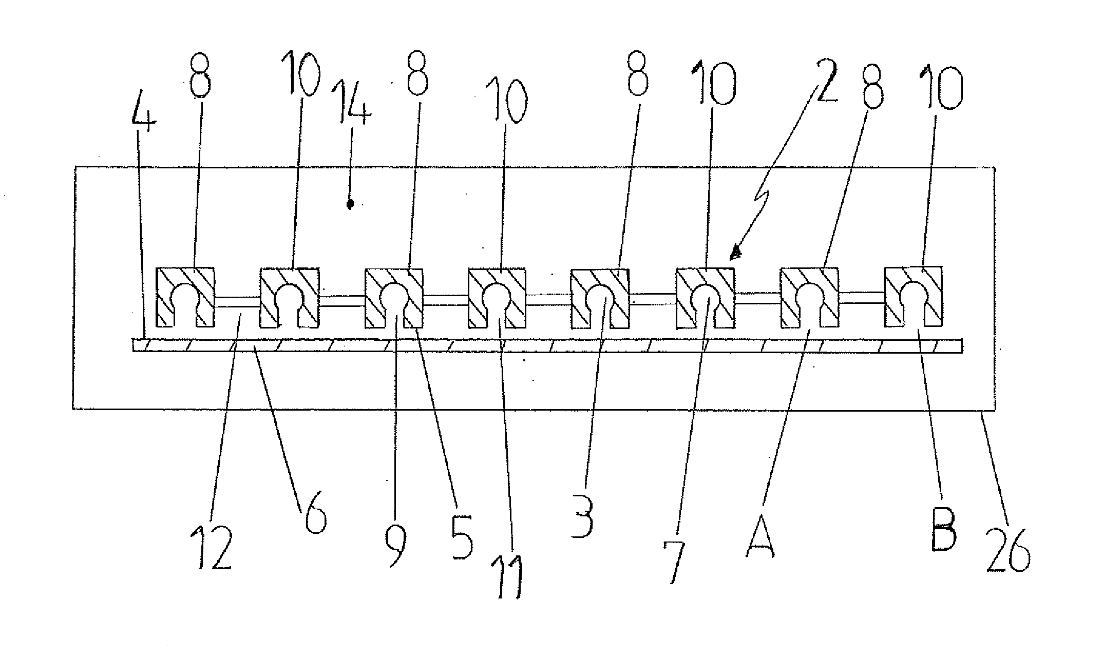
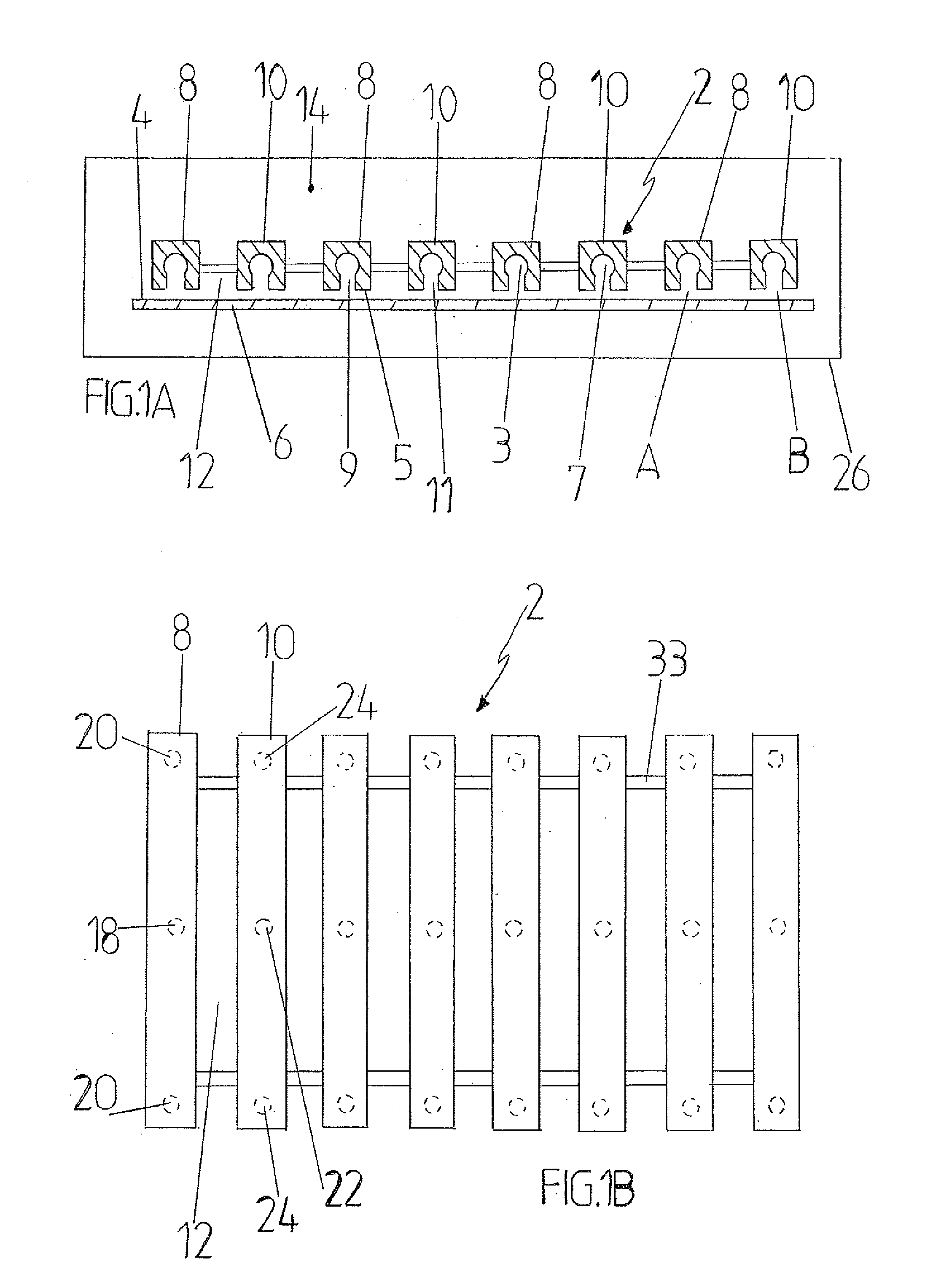
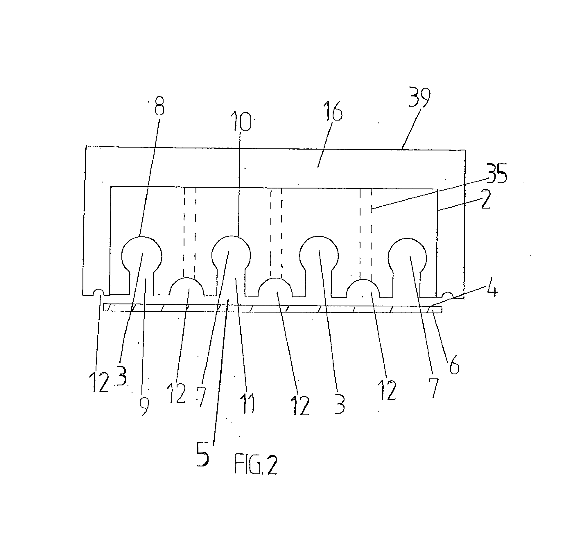
[0016]FIG. 1 shows a cross sectional view of one embodiment of an apparatus for subjecting a surface 4 of a substrate 6 to successive surface reactions of at least a first precursor A and a second precursor B according to the principles of ALD. The first and second precursors A and B may be any gaseous precursors used in ALD, such as ozone, TMA (trimethylaluminium), water, TiCl4, DEZ (diethylzinc), or precursor may also be plasma, such as NH3, Ar, O2, N2, H2 or CO2 plasma. The apparatus comprises a process chamber 26 having inside a gas atmosphere 14. The gas atmosphere 14 may comprise inert gas, such as nitrogen, or dry air, or any other gas suitable to be used as purge gas in ALD method. Also plasma may be used for purging, for example nitrogen or argon plasma. In that this context purge gas comprises also plasma. The purge gas source is connected to process chamber 36 for supplying purge gas into the process chamber 26. A nozzle head 2 is arranged inside the process chamber 26. T...


PUM

PropertyMeasurementUnit
pressureaaaaaaaaaa
pressuresaaaaaaaaaa
air pressureaaaaaaaaaa

Abstract

Described herein is an apparatus and nozzle head for coating a surface of a substrate. The apparatus comprising a process chamber having inside a gas atmosphere, a nozzle head arranged inside the process chamber, precursor supply and discharge means. The nozzle head including one or more first precursor nozzles for subjecting the surface of the substrate to the first precursor, one or more second precursor nozzles for subjecting the surface of the substrate to the second precursor and one or more purge gas channels between the first and second precursor zones. In certain aspects, the purge gas channel is at least partly open to the gas atmosphere comprising purge gas for subjecting the surface of the substrate to purge gas.

Description

BACKGROUND OF THE INVENTION[0001]The present invention relates to a nozzle head for subjecting a surface of a substrate to successive surface reactions of at least a first precursor and a second precursor, and particularly to a nozzle head according to the preamble of claim 1. The present invention further relates to a an apparatus comprising a nozzle head for subjecting a surface of a substrate to successive surface reactions of at least a first precursor and a second precursor, and particularly to an apparatus according to the preamble of claim 17. The present invention also relates to a method for subjecting a surface of a substrate to successive surface reactions of at least a first precursor and a second precursor, and particularly to a method according to the preamble of claim 25.[0002]In the prior art several types of apparatuses, nozzle heads and nozzles are used for subjecting a surface of a substrate to successive surface reactions of at least a first precursor and a secon...

Claims


Application Information

Patent Timeline
Patent Type & Authority Applications(United States)
IPC IPC(8): C23C16/455
CPCC23C16/45551C23C16/545C23C16/45563
Inventor SOININEN, PEKKAPEKONEN, OLLI
Owner BENEQ OY
Learn More