
Channel state feedback for multi-cell MIMO

Active Publication Date: 2013-06-13
FUJITSU LTD
View PDF14 Cites 32 Cited by
  • Summary
  • Abstract
  • Description
  • Claims
  • Application Information

AI Technical Summary

Benefits of technology

This patent discusses a method to reduce the amount of CSI reports in wireless communication networks. By co-operating with multiple cells, the amount of CSI reports can be reduced compared to each cell being the subject of a CSI report. This reduces the amount of uplink resource used for feeding back CSI. The method involves finding a "best" cell with which the user equipment should communicate and reporting on one or more other cells. This helps to avoid wasting resources on CSI reports for cells that are not significant for the current user communications. Additionally, the method allows the network to trigger the user equipment to select and send the CSI reports for the "best" cell and at least one other cell based on a reference signal received by the user equipment. This ensures that the CSI report for the "best" cell is the most timely.

Problems solved by technology

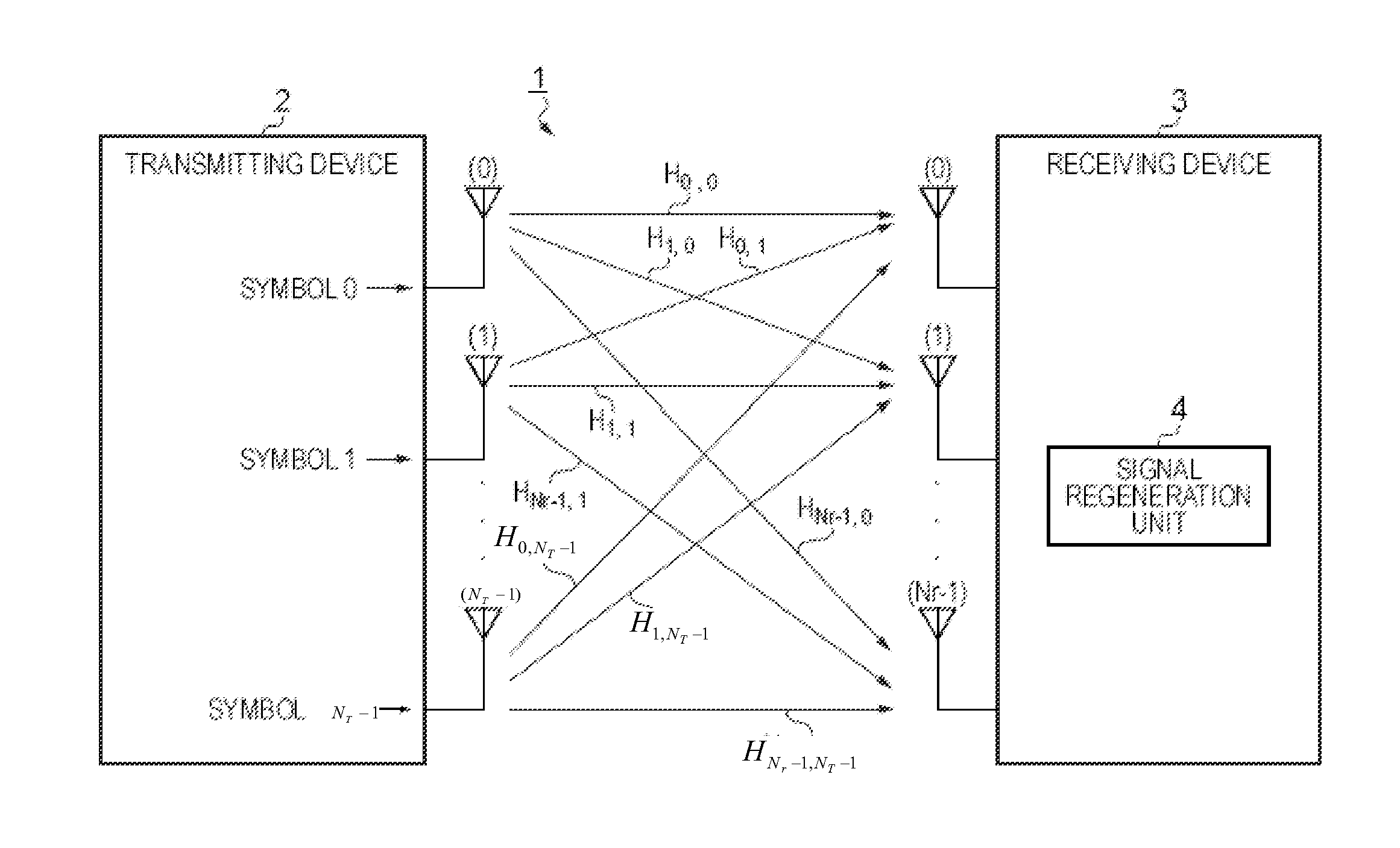
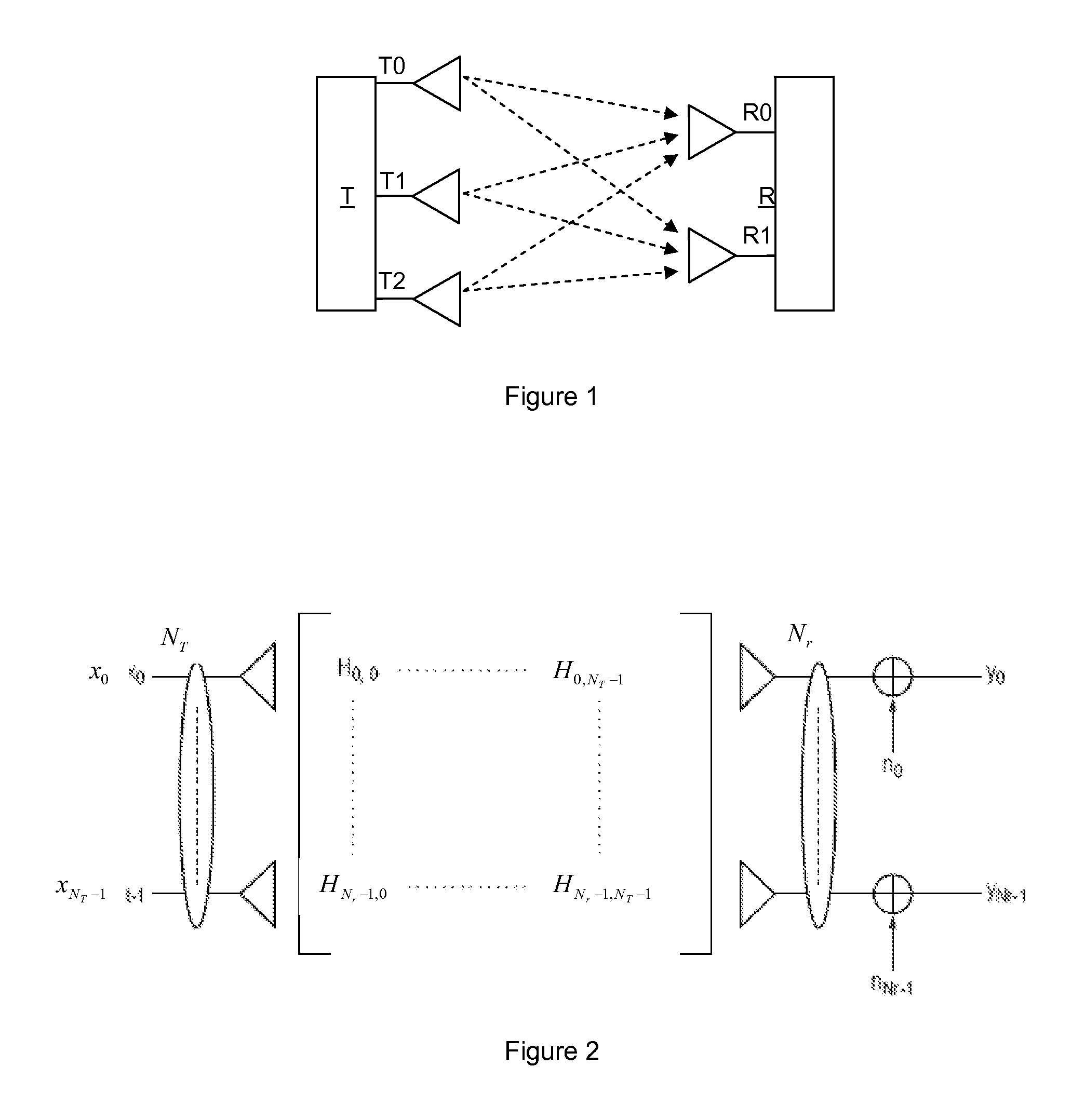
Typically, a BS in a wireless communication system will be equipped with many more antennas in comparison with a UE (such as, for example, a mobile handset), owing to differences in power, cost and size limitations.
In the non-adaptive case, the transmitter does not have any knowledge of the channel properties and this limits performance, as it cannot take account of changes in conditions which cause changes in the state of the channel.
However, it may not always be desirable to incur the overhead of uplink sounding, in which case closed-loop techniques offer an alternative.
However, in the more elaborate multi-cellular networks discussed in the previous paragraph, the benefits of MIMO transmission can often be limited by inter-cell interference.
Inter-cell interference may arise, for example, because the frequency resources (i.e. the carriers and subcarriers) utilised by base stations in transmitting data to user equipments in one cell are identical to the frequency resources utilised by base stations in transmitting data to user equipments in an adjacent cell.
And because common frequency resources may be used in adjacent cells (i.e. there is simultaneous use of substantially identical transmission frequencies in adjacent cells), signals being transmitted in the adjacent cells can often interfere with data being transmitted to the cell-edge user.
However, the trade-off for this improvement is that the coordination of transmissions in multi-cellular MIMO systems requires channel state information (CSI) and data information to be shared among the coordinated base stations.
This in turn results in a significant additional burden on the system's transmission and data capacity resources.
As also explained above, for FDD systems, to achieve equivalent detail of channel knowledge for each cell, the total amount of channel information needed to be fed back increases linearly with the number of cooperating cells (or sectors of cells), and this creates a heavy additional burden for the uplink channel particularly.

Method used


Image

  • Channel state feedback for multi-cell MIMO
  • Channel state feedback for multi-cell MIMO
  • Channel state feedback for multi-cell MIMO

Examples


Embodiment Construction

[0116]In the above explanation, the term “channel” (as in MIMO channel) has been used to describe the response of the entire radio link between a transmitter and a receiver. However, the term “channel” is also used in another sense to denote capacity reserved on the uplink, or downlink, for various purposes. Such channels can be defined at various levels of abstraction within the network. FIG. 8 shows some of the channels defined in LTE at each of a logical level, transport layer level and physical layer level, and the mappings between them. For present purposes, the channels at the physical layer level are of particular interest.

[0117]On the downlink, user data is carried on the Physical Downlink Shared Channel (PDSCH). There are various control channels on the downlink, which carry signaling for various purposes. In particular the Physical Downlink Control Channel, PDCCH, is used to carry scheduling information from base stations (called eNodeBs in LTE) to individual UEs.

[0118]Mea...


PUM


Abstract

A method is disclosed which is intended for use in multiple-input multiple-output wireless communication systems which have a plurality of adjacent cells (cell A, cell B, cell C, cell D), each containing one or more base stations which co-operatively transmit signals to, and receive signals transmitted from, a user equipment (UE). The user equipment is operable to feed back to the relevant base station(s) CSI reports relating to channel(s) between the relevant base station(s) and the users, the base stations are operable to adapt signals for transmission to users, based on the fed back channel state information. The method involves the UE being configured to select at least one cell to be the subject of a CSI report, and to send the CSI report with an indication of the subject cell(s). Feedback overhead on the uplink is reduced when many cells co-operate in transmission to the user equipment.

Description

CROSS-REFERENCE TO RELATED APPLICATION[0001]This application is based upon and claims the benefit of priority of the prior International Patent Application No. PCT / EP2010 / 062971, filed on Sep. 3, 2010, the entire contents of which are wholly incorporated herein by reference.FIELD OF THE INVENTION[0002]The present invention relates to wireless communication systems, and in particular to multi-cell multiple-input multiple-output (“MIMO”) systems in which there is coordination of transmissions between cells, for example systems compliant with the 3GPP Long Term Evolution (LTE), 3GPP LTE-A, IEEE 802.16 and 802.11 groups of standards.BACKGROUND OF THE INVENTION[0003]Wireless communication systems are widely known in which base stations (BSs) communicate with user equipments (UEs) (also called subscriber or mobile stations) within range of the BSs.[0004]The geographical area covered by one or more base stations is generally referred to as a cell, and typically many BSs are provided in app...

Claims


Application Information

Patent Timeline
IPC IPC(8): H04W72/04
CPCH04B7/024H04B7/0417H04W72/0413H04B7/0658H04B7/0626H04W72/21
Inventor MOULSLEY, TIMOTHYVADGAMA, SUNIL KESHAVJI
Owner FUJITSU LTD
Learn More