RTWO-Based Pulse Width Modulator

Active Publication Date: 2013-06-13
ANALOG DEVICES INC
View PDF0 Cites 2 Cited by
  • Summary
  • Abstract
  • Description
  • Claims
  • Application Information

AI Technical Summary

Benefits of technology

The invention has several advantages. Firstly, it eliminates a specific type of loss in the circuit, and instead requires a small amount of additional power. Secondly, it allows components to be made smaller because they can operate at very high frequencies. Thirdly, it makes it easy to drive synchronous rectifiers from the same switches. Fourthly, it allows for optimum timing of synchronous rectifiers without incurring additional penalties. Fifthly, it allows for use of poly phase power supplies without significant increase in loss. Finally, it allows devices to operate in series.

Problems solved by technology

Instead, a small RTWO power overhead is incurred, as the capacitances of the switches become part of the capacitance of the RTWO.

Method used


Image

  • RTWO-Based Pulse Width Modulator
  • RTWO-Based Pulse Width Modulator
  • RTWO-Based Pulse Width Modulator

Examples


embodiment 270

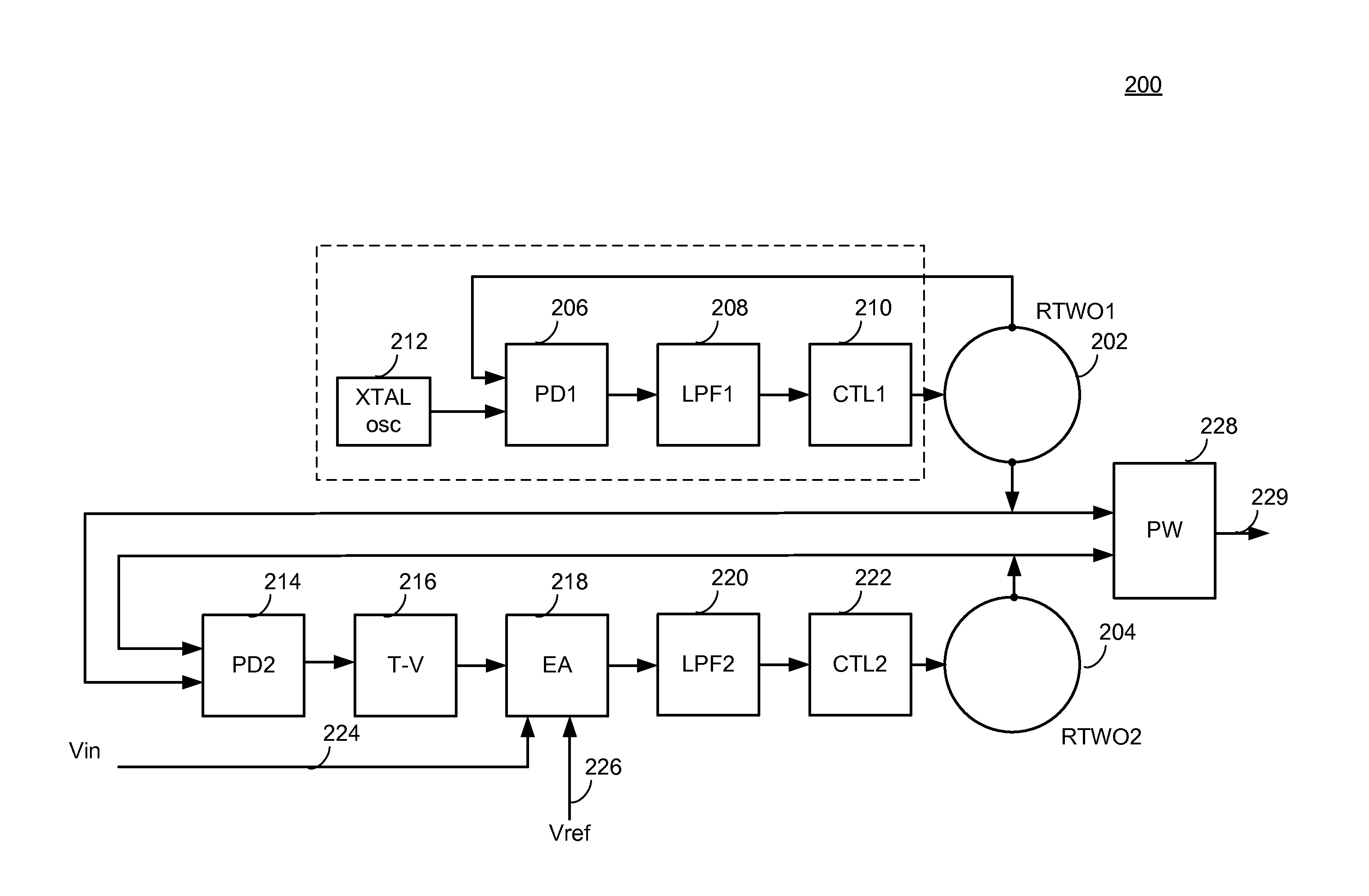
[0039]Block PW 228 in FIGS. 2A and 2B combines selected output taps of RTWO1202 and RTWO2204. The output 229 of the PW block 228 is thus a pulse whose width is modulated by the input Vin 224. FIG. 2D shows an embodiment 270 of the PW block. Instead of using a single switching transistor, two transistors 272, 274 are used in series. The top transistor in the series receives the output of RTWO1202. The bottom transistor receives the output of RTWO2204. The pair of transistors 276 has an on time that is the overlap of the two RTWO outputs, as shown. An alternative to two transistors is a single transistor with dual gates (MOSFET) or bases (BJT), although such transistors are less common.

[0040]FIG. 2B shows an alternative design 240 in which the phase offset is digitally controlled. In this embodiment, the operation of RTWO1202 is the same as in the embodiment of FIG. 2A. The blocks for controlling the phase offset derived from RTWO2 are different. These blocks include a PD2 block 242, ...

embodiment 300

[0041]FIG. 2C shows a more simple embodiment 300 for digitally controlling the pulse width, which is illustrated conceptually in FIG.3. This embodiment includes an A / D block 302, a PS block 304 and a PW block 306, along with a single RTWO 308. The A / D block 302 receives the voltage Verror 310 to generate a digital version [d1, d2, . . . ,dn]312 of the control voltage. The digital version of the control voltage [d1, d2, . . . ,dn]312 operates to select one of N phases tapped directly from the RTWO 308 via the PS block 304. The PW block 306 recieves the selected phase 316 from the RTWO 308 along with a phase from a fixed tap 314 of the RTWO and operates to combine the phases to create the desired pulse width.

Power Converter Design

[0042]FIG. 4A shows the pulse width modulator used in a power converter 400. The input voltage Vin 402 connects to the output voltage 404 of the converter via a scaler block 406, which may increase or decrease the load voltage 404, and the output of the PW bl...


PUM


Abstract

A pulse width modulator based on a pair of rotary traveling wave oscillators. The first oscillator operates freely or as part of a phase-locked loop. The second oscillator operates at the same frequency as the first oscillator, but with a controllable phase offset from the first oscillator. The phase offset is set by an input voltage. A block takes the outputs of the first and second oscillators and combines them so that the output is a pulse whose width is the overlap of the oscillation signals from the first and second oscillators. The ouput pulse width is thus a function of the input voltage. When the pulse width modulator receives the input voltage from the output of a switching power supply, it can use the modulated pulse width to control the switching transistor of the power supply to maintain the output at a regulated voltage.

Description

CROSS-REFERENCE TO RELATED APPLICATIONS[0001]1. Field of the Invention[0002]The present invention relates generally to pulse width modulators and more specifically to pulse width modulators employing at least one rotary traveling wave oscillator.[0003]2. Description of the Related Art[0004]DC to DC converters commonly include a switching transistor connected to a filter circuit and a control circuit. FIG. 1A shows a simple converter configuration 100. The converter includes a switching transistor 102, a diode 104, an inductor 106, and a capacitor108. The switching transistor 102 is connected between the primary energy source 110, such as a battery, and a low pass filter circuit 112, which is formed by the inductor 106 and capacitor 108, as shown. In this type of converter, the inductor 106 also functions as an energy storage element. The capacitor 108 is connected across the load 112 and is used to filter out voltage variations (ripple) at the load 112 that would otherwise occur. Ty...

Claims


Application Information

Patent Timeline
IPC IPC(8): H03K7/08
CPCH02M3/156H03K7/08
Inventor BECCUE, STEPHENMARTCHOVSKY, ANDREY
Owner ANALOG DEVICES INC
Why Eureka
Try Eureka