
Audio testing system and audio testing method for device under test

Inactive Publication Date: 2013-06-06
INVENTEC CORP
View PDF4 Cites 17 Cited by
  • Summary
  • Abstract
  • Description
  • Claims
  • Application Information

AI Technical Summary

Benefits of technology

The present invention is an audio testing system and method for electronic devices that allows for automatic, unbased testing without the need for human ears. This avoids complicated and detailed steps, reduces faults, and prevents misjudgment. The system sends testing audio and controls the device under test to record and play back the audio, using existing technology to generate testing results. This system improves efficiency and reduces potential miscalculations during production.

Problems solved by technology

For manufacturers, how to detect a tone quality of a portable electronic device (for example, an audio playback device such as a notebook computer, a cell phone, and a tablet) on a production line is always an important issue.
However, in the prior art, the manufacturers need to purchase many complicated and expensive instruments to perform testing on the audio playback devices, which not only causes the increase of manufacturing cost, but has a complicated and time-consuming operation, and is not suitable to be performed on the production line.
As for the current audio testing manner, a part of the testing content needs to be judged by human ear of testers, and noises on the production line always disturbs other testers nearby.
Therefore, the manner of recognizing the audio with human ears does not have a unified standard and is easy to generate large error, so it is hard to avoid misjudgement of the testers.

Method used


Image

  • Audio testing system and audio testing method for device under test
  • Audio testing system and audio testing method for device under test
  • Audio testing system and audio testing method for device under test

Examples


Embodiment Construction

[0017]Reference will now be made in detail to the present embodiments of the invention, examples of which are illustrated in the accompanying drawings. Wherever possible, the same reference numbers are used in the drawings and the description to refer to the same or like parts.

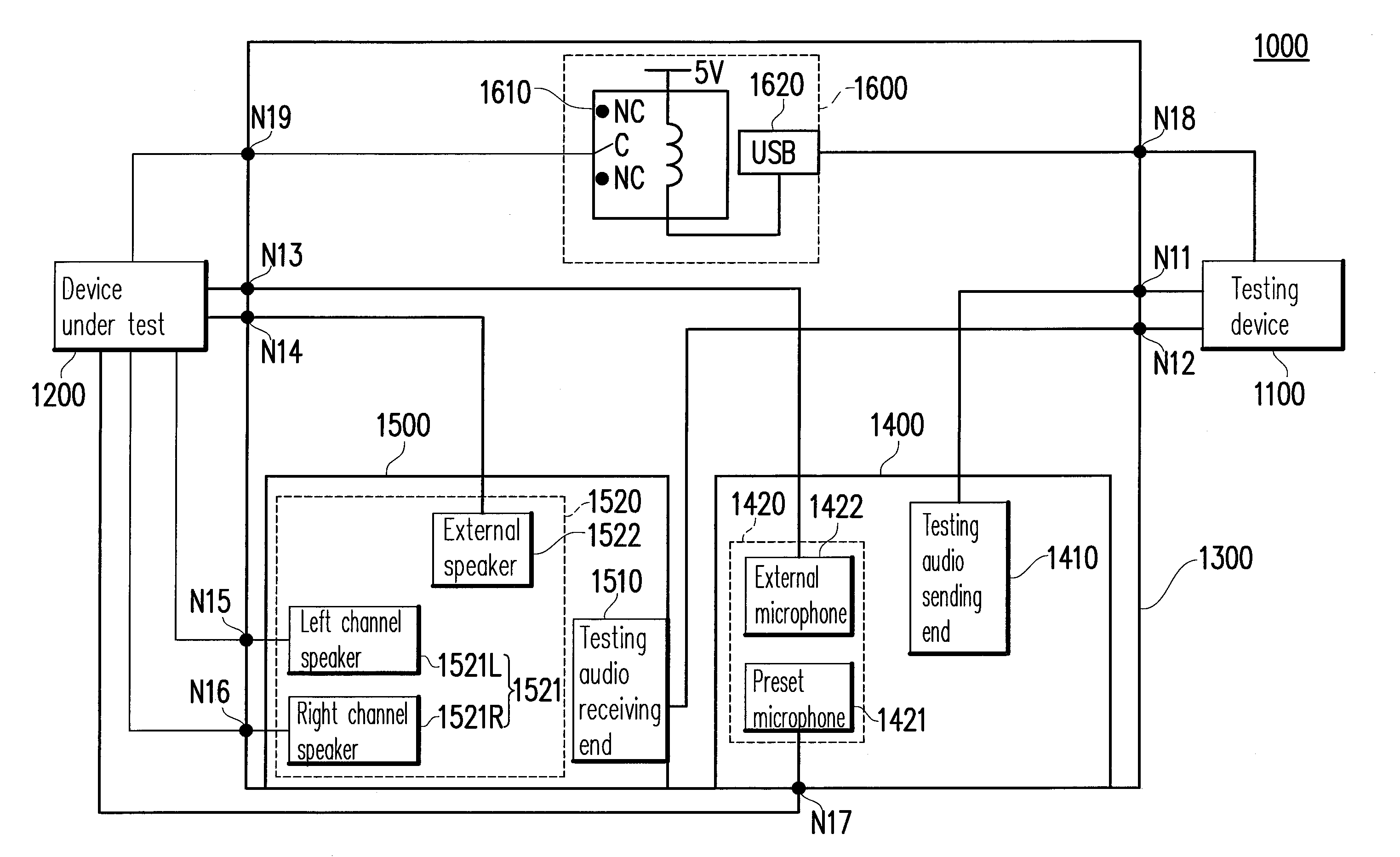
[0018]FIG. 1 is a block diagram of an audio testing system 1000 according to an embodiment of the present invention. Referring to FIG. 1, the audio testing system 1000 provided in the present invention includes a testing device 1100, an electronic device under test 1200, a jig 1300, and an interface circuit 1600. The testing device 1100 includes a testing audio sending end 1410 and a testing audio receiving end 1510.

[0019]The device under test 1200 includes an audio receiving end 1420 and both-side audio sending ends 1520. The interface circuit 1600 includes a testing switch 1610 and a universal serial bus (USB) interface 1620.

[0020]During the implementation, the audio testing system 1000 mainly tests the devi...


PUM


Abstract

An audio testing system and an audio testing method for an electronic device under test are provided. The audio testing method includes the following steps. A testing audio is sent through a testing audio sending end of a testing device. An electronic device under test is controlled to perform recording through an audio receiving end, so as to generate an under-testing audio. After the recording is completed, the device under test controlled to playback the under-testing audio from one of both-side audio sending ends to perform recording through the testing audio receiving end, and calls an audio analyzing process to generate a first testing result. The device under test controlled to playback the under-testing audio from the other one of the both-side audio sending ends to perform recording through the testing audio receiving end, and calls the audio analyzing process to generate a second testing result.

Description

CROSS-REFERENCE TO RELATED APPLICATION[0001]This application claims the priority benefit of Taiwan application serial no. 100144637, filed on Dec. 5, 2011. The entirety of the above-mentioned patent application is hereby incorporated by reference herein and made a part of this specification.BACKGROUND OF THE INVENTION[0002]1. Field of the Invention[0003]The present invention generally relates to a testing technique, in particular, to an audio testing system and an audio testing method for an electronic device under test.[0004]2. Description of Related Art[0005]For manufacturers, how to detect a tone quality of a portable electronic device (for example, an audio playback device such as a notebook computer, a cell phone, and a tablet) on a production line is always an important issue. In order to ensure the audio quality of products thereof, the manufacturers perform various detections on audio loops of the products, and the detections include measuring the following items of the audi...

Claims


Application Information

Patent Timeline
IPC IPC(8): H04R29/00
CPCH04R5/04H04R2420/01H04R29/004H04R29/001
Inventor YANG, TSUNG-HAOSIEK, HARIANTOWANG, SHAO-TANG
Owner INVENTEC CORP
Learn More