Methods for Removing Polymer Skins from Reactor Walls
- Summary
- Abstract
- Description
- Claims
- Application Information
AI Technical Summary
Benefits of technology
Problems solved by technology
Method used
Image
Examples
examples
[0116]The invention is further illustrated by the following examples, which are not to be construed in any way as imposing limitations to the scope of this invention. Various other aspects, embodiments, modifications, and equivalents thereof which, after reading the description herein, can suggest themselves to one of ordinary skill in the art without departing from the spirit of the present invention or the scope of the appended claims.
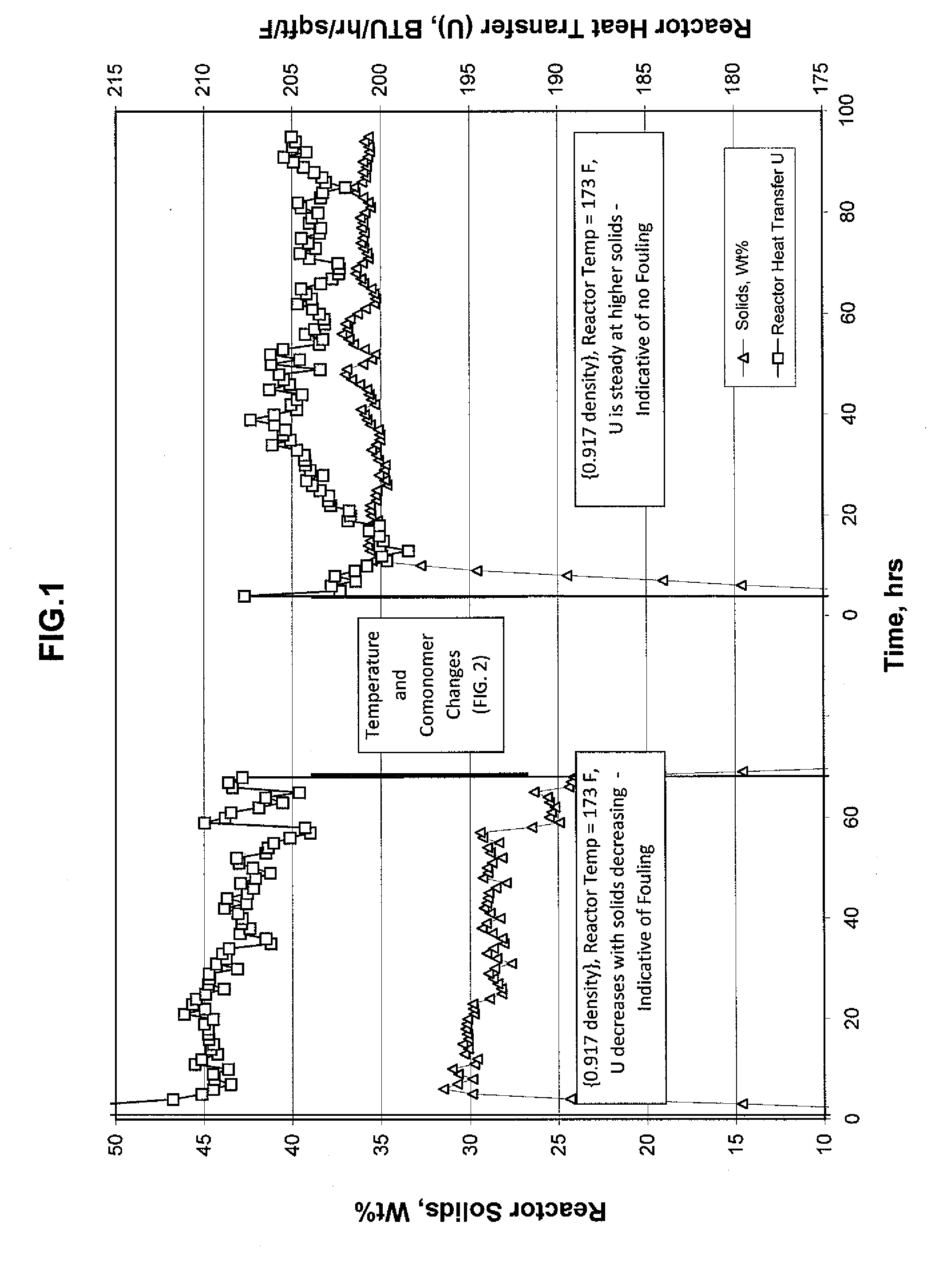
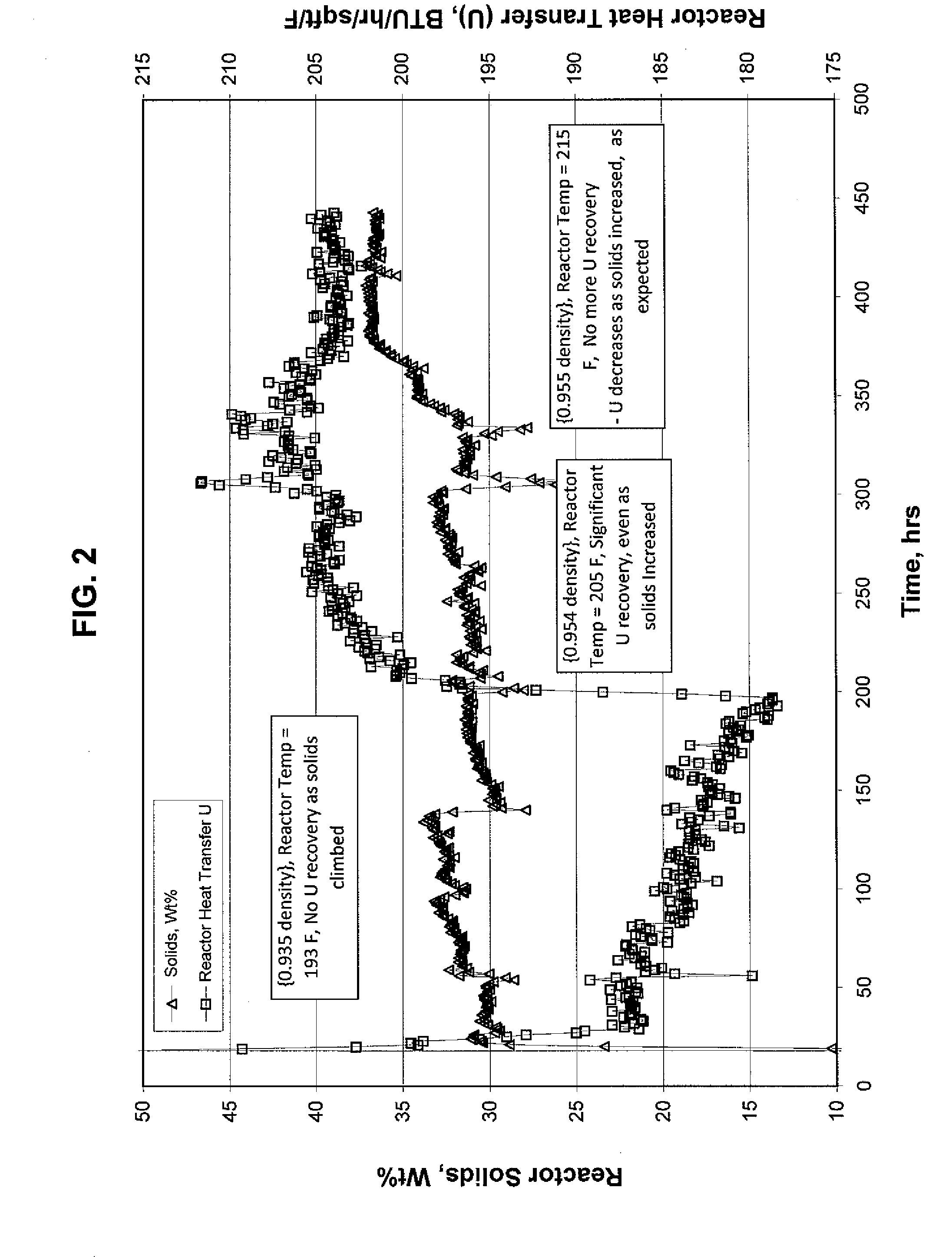
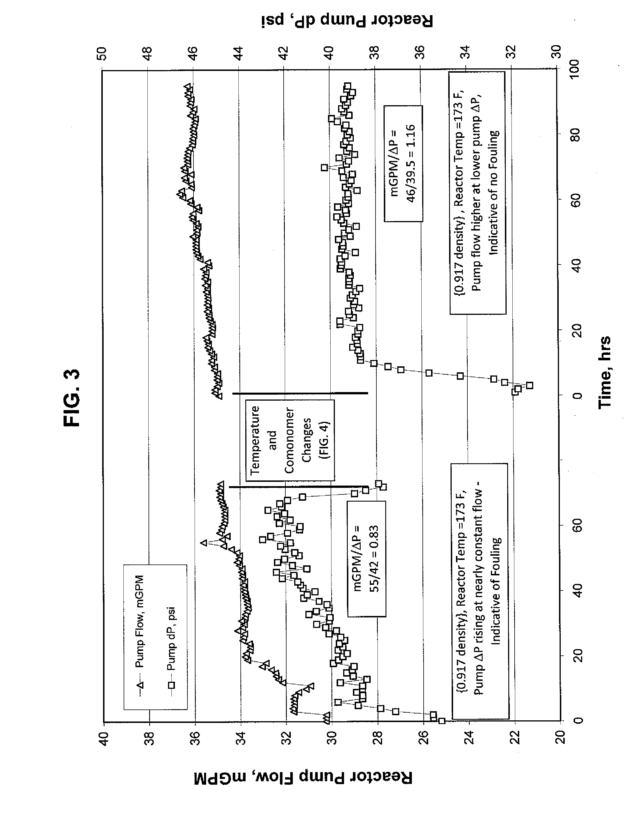
[0117]A large scale experimental trial was conducted to determine the impact of a combination of increasing density (removal of comonomer) and increasing polymerization temperature on removing polymer skins from reactor walls in a loop slurry reactor.
[0118]Referring to FIGS. 1, 3, and 5, an ethylene / 1-hexene copolymer having a nominal 0.917 g / cc density was produced. The catalyst composition was a metallocene-based catalyst composition comprising about 3.5-4 wt. % of a metallocene compound on a solid acid activator. The reactor size was about 27,000 ...
embodiment 1
[0123]A method for removing polymer skins from reactor walls in a polymerization reactor system comprising a loop slurry reactor, the method comprising:
[0124](i) contacting a catalyst system, an olefin monomer, and an olefin comonomer in the loop slurry reactor under polymerization conditions to produce an olefin copolymer;
[0125](ii) removing some or all of the olefin comonomer to produce an olefin polymer having a density at least 0.015 g / cc higher than the olefin copolymer density; and
[0126](iii) increasing a polymerization temperature of the loop slurry reactor by at least 6° C. (11° F.);
[0127]wherein a heat transfer coefficient of the loop slurry reactor increases by at least 28 W / m2 / ° C. (4.9 BTU / hr / ft2 / ° F.).
embodiment 2
[0128]A method for removing polymer skins from reactor walls in a polymerization reactor system comprising a loop slurry reactor, the method comprising:
[0129](I) a first polymerization step comprising contacting a catalyst system, an olefin monomer, and a first olefin comonomer in the loop slurry reactor under first polymerization conditions to produce an olefin copolymer;
[0130](II) a second polymerization step comprising (a) removing some or all of the first olefin comonomer to produce an olefin polymer having a density at least 0.015 g / cc higher than the olefin copolymer density; and (b) increasing a polymerization temperature of the loop slurry reactor by at least 6° C. (11° F.); and
[0131](III) a third polymerization step comprising contacting the catalyst system, the olefin monomer, and the first olefin comonomer in the loop slurry reactor under conditions substantially the same as the first polymerization conditions to produce the olefin copolymer;
[0132]wherein a heat transfer ...
PUM
| Property | Measurement | Unit |
|---|---|---|
| Temperature | aaaaa | aaaaa |
| Temperature | aaaaa | aaaaa |
| Temperature | aaaaa | aaaaa |
Abstract
Description
Claims
Application Information
 - R&D
- Intellectual Property
- Life Sciences
- Materials
- Tech Scout
- Unparalleled Data Quality
- Higher Quality Content
- 60% Fewer Hallucinations
Browse by: Latest US Patents, China's latest patents, Technical Efficacy Thesaurus, Application Domain, Technology Topic, Popular Technical Reports.
© 2025 PatSnap. All rights reserved.Legal|Privacy policy|Modern Slavery Act Transparency Statement|Sitemap|About US| Contact US: help@patsnap.com


