
Centrifugal compressor

a centrifugal compressor and compressor technology, which is applied in the direction of machines/engines, stators, liquid fuel engines, etc., can solve the problems of limited pressure ratio, limited pressure in the inlet of the motor, and limited pressure ratio of the conventional centrifugal compressor, so as to achieve low speed and improve the pressure ratio

Inactive Publication Date: 2013-05-30
KANGYUE TECH
View PDF3 Cites 12 Cited by
  • Summary
  • Abstract
  • Description
  • Claims
  • Application Information

AI Technical Summary

Benefits of technology

The invention is a compression device that can improve pressure ratio and response at low speeds. Compared to conventional centrifugal compressors, the invention can perform work on air for three times, effectively improving the pressure ratio. The centrifugal compressor is important for solving problems in the impeller material strength in high supercharging fields. The front and rear cascades are driven by the motor, and are independently of the centrifugal impeller. This helps to control the rotational speed of the motor and improve the compressor's performance even when the impeller cannot rotate at high speeds.

Problems solved by technology

However, restricted by the size, the conventional turbocharger can only employ a single centrifugal impeller to process the air.
Thus, to improve the pressure in the inlet of the motor by improving the pressure ratio of the conventional centrifugal compressor is largely limited.
Furthermore, because the size limitation, it is difficult to develop a multiple compression technology.

Method used


Image

  • Centrifugal compressor
  • Centrifugal compressor
  • Centrifugal compressor

Examples


example 1

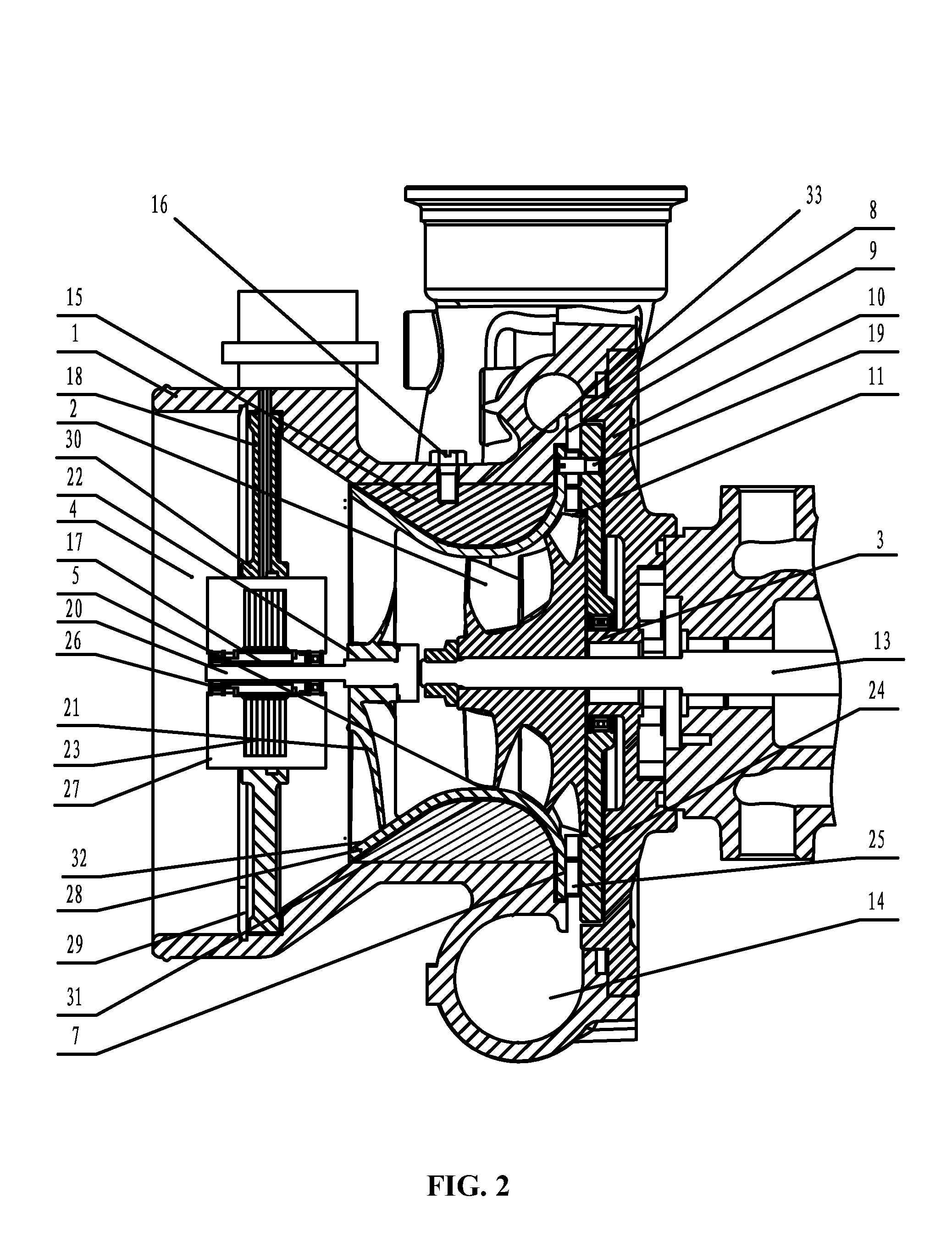
[0038]As shown in FIG. 2, a centrifugal compressor comprises a housing 1. The housing 1 comprises: a flow channel 14, an inlet 4, an impeller outlet 11, and an air diffusing channel 9. A turbine shaft 13 is disposed inside the housing 1, and the centrifugal impeller 2 is mounted on the turbine shaft 13. The impeller outlet 11 is disposed adjacent to a rear part of the centrifugal impeller 2 and connected to the flow channel 14 via the air diffusing channel 9.

[0039]A rotating wall 28 is disposed between the centrifugal impeller 2 and the housing 1, and an axial section of the rotating wall 28 is in a shape of a dumbbell. A front cascade 21 is disposed inside a front wall of the rotating wall 28 and is in rigid connection with a dynamic driving device.

[0040]A rotating disc 24 is disposed inside the housing 1 adjacent to the air diffusing channel 9, and in rigid connection with the rotating wall 28. A rear cascade 25 is arranged on the rotating disc 24.

[0041]A first diffusing wall 10 i...

example 2

[0061]The present example is different from Example 1 only in mounting angles of the front blades 5 and the rear blades 12.

[0062]As shown in FIG. 7, the front cascade 21, the rotating wall 28, the rear cascade 25, and the rotating disc 24 are driven by the motor shaft 20, and rotate in the same rotary direction as the turbine shaft. In correspondingly, mounting angles of the front cascade 21 and the rear cascade 25 are adjusted. Structures of other components are the same as Example 1.

[0063]As shown in FIG. 8, the turbine shaft 13 rotates along a Y2 direction. The front blades 21, the rotating wall 28, the rear blades 12, and the rotating disc 24 are driven by the motor shaft 20 and coaxially rotate in the same direction as the turbine shaft 13, that is, the rotary direction of the motor shaft 20 is also Y2.

[0064]As shown in FIG. 9, each front blade 5 is in a shape of an aerofoil, and comprises: a front edge 34, and a rear edge 35. The front edge 34 bends towards a rotary direction ...


PUM


Abstract

A centrifugal compressor, including: a housing, the housing including: an inlet, a flow channel, an impeller outlet, and an air diffusing channel; a centrifugal impeller disposed inside the housing; a rotating wall, the rotating wall including a front cascade; and a rotating disc, the rotating disc including a rear cascade. The impeller outlet is disposed adjacent to a rear part of the centrifugal impeller and is connected to the flow channel via the air diffusing channel. The rotating wall is disposed between the centrifugal impeller and the housing. The front cascade is disposed inside the front part of the rotating wall and is connected to a dynamic driving device. The rotating disc is disposed inside the housing adjacent to the air diffusing channel and is in a rigid connection with the rotating wall.

Description

CROSS-REFERENCE TO RELATED APPLICATIONS[0001]This application is a continuation-in-part of International Patent Application No. PCT / CN2010 / 002168 with an international filing date of Dec. 27, 2010, designating the United States, now pending, and further claims priority benefits to Chinese Patent Application No. 201010238156.5 filed Jul. 28, 2010. The contents of all of the aforementioned applications, including any intervening amendments thereto, are incorporated herein by reference. Inquiries from the public to applicants or assignees concerning this document or the related applications should be directed to: Matthias Scholl P.C., Attn.: Dr. Matthias Scholl Esq., 14781 Memorial Drive, Suite 1319, Houston, Tex. 77079.BACKGROUND OF THE INVENTION[0002]1. Field of the Invention[0003]The invention relates to a compression device for an internal combustion engine, and more particularly to a centrifugal compressor for a vehicular turbocharger.[0004]2. Description of the Related Art[0005]I...

Claims


Application Information

Patent Timeline
IPC IPC(8): F04D17/10
CPCF04D25/0606F04D27/007F04D27/0292F04D29/464F04D17/10F04D29/444F04D17/127F04D19/024F04D29/4213F05D2250/52F05D2250/51
Inventor WANG, HANGMA, CHAOZHU, ZHIFULI, YONGTAISONG, LIHUAGUO, XILUWANG, CONGCONG
Owner KANGYUE TECH
Learn More