
Membrane-augmented distillation with compression to separate solvents from water

a membrane-augmented and solvent technology, applied in vacuum distillation separation, carboxylic compound preparation, separation process, etc., can solve the problems of high cost and complicated production of dry solvents from raw aqueous mixtures, and achieve the effects of low energy consumption, increased flexibility in heat exchange choices, and reduced cos

Active Publication Date: 2012-02-14
ENVIRONMENTAL PROTECTION AGENCY US +1
View PDF18 Cites 21 Cited by
  • Summary
  • Abstract
  • Description
  • Claims
  • Application Information

AI Technical Summary

Benefits of technology

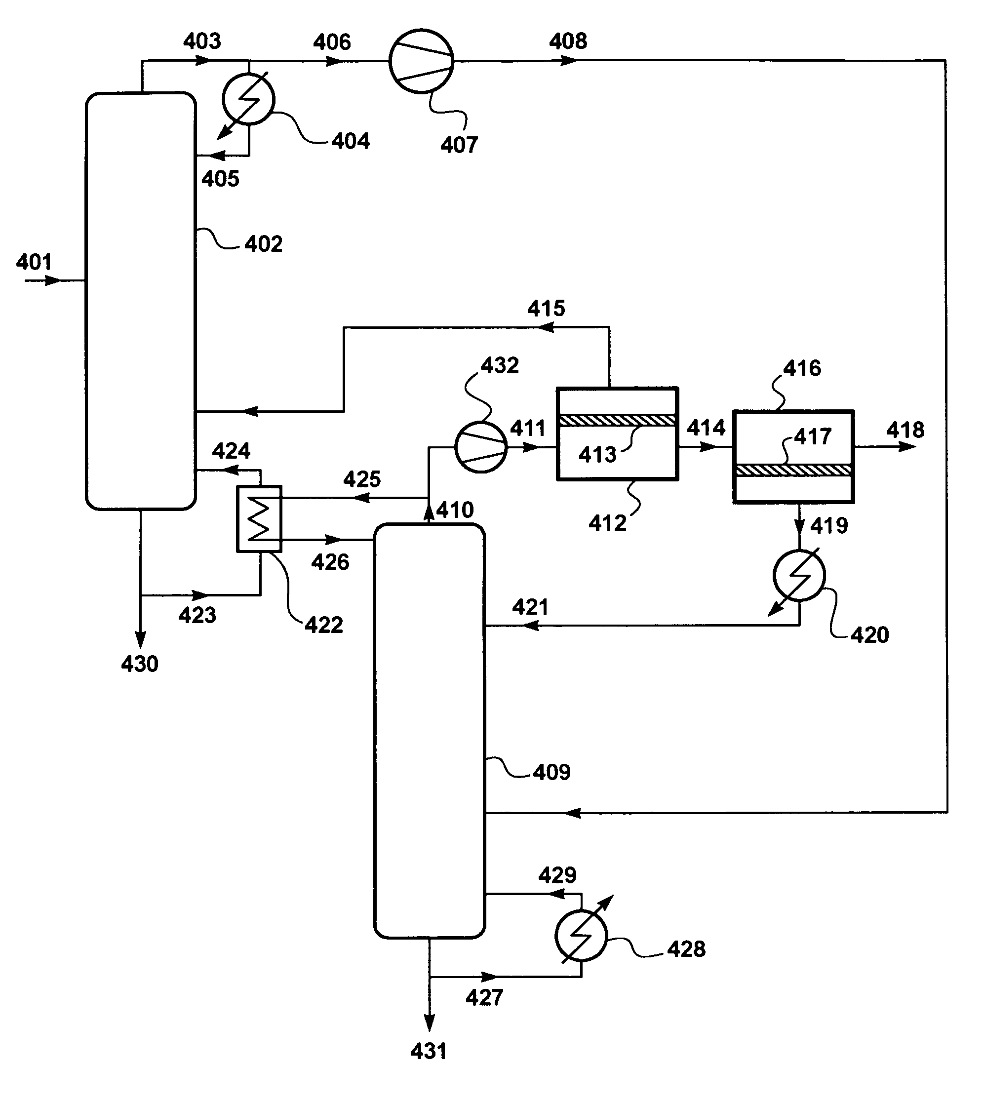
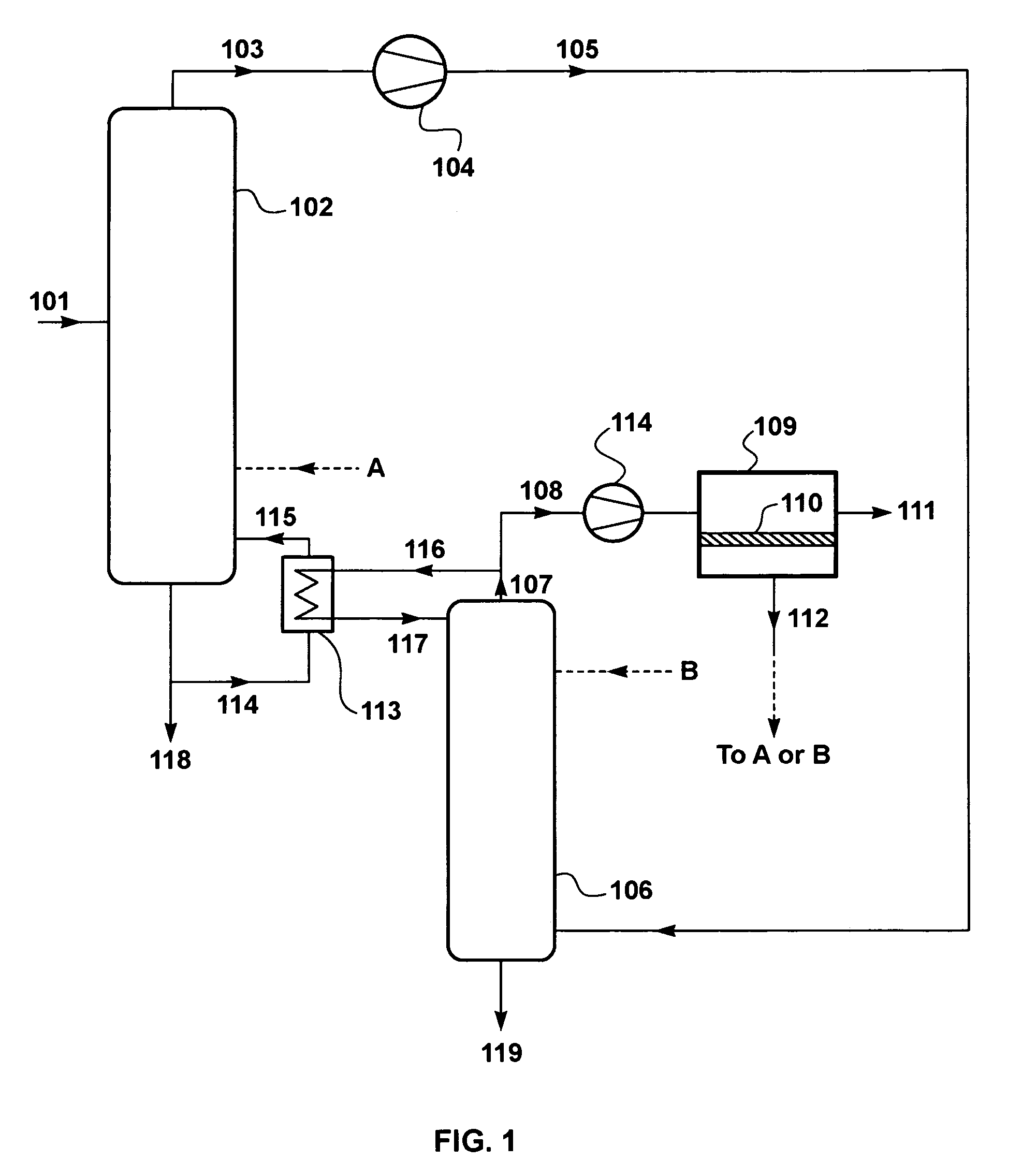
[0011]The process incorporates two distillation steps in series, operated at different pressures, followed by one or two membrane separation steps. The steps are integrated in such a way as to provide an operation that has both good energy efficiency and controlled capital costs.
[0021]The membrane separation step operates under a pressure difference between the feed and permeate sides of the membranes. The step divides the overhead stream into a residue stream, which is the dehydrated product of the process, and a permeate stream. To increase the driving force for transmembrane permeation, it is preferred to maintain the permeate side of the membranes under a partial vacuum. This also improves the pressure ratio for this step, which makes for a better separation between stream components.
[0022]The pressure ratio may be increased by using a vacuum pump in the permeate line to pull a vacuum on the permeate side. Preferably, the permeate stream is condensed, thereby creating the desired partial vacuum. The condensed stream is then passed to the first or second distillation step in liquid form. Return of the permeate in either vapor or liquid form within the process increases the overall heat recovery.
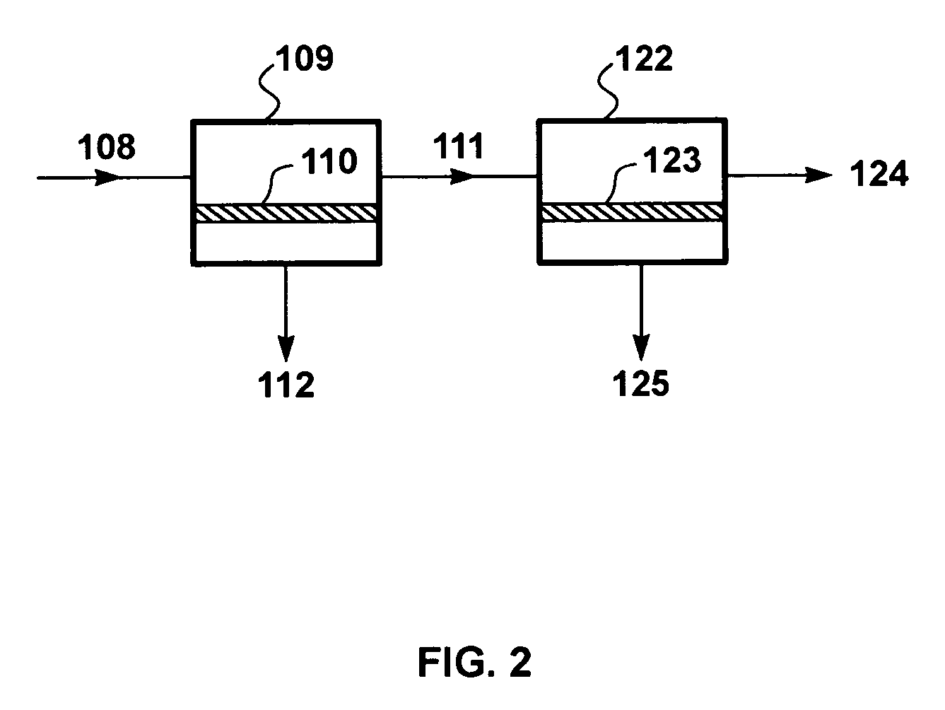
[0025]More than one membrane separation step may optionally be used. Use of two membrane separation steps, with the residue from the first step forming the feed to the second, provides greater flexibility to tailor the process to control total energy usage and compressor capacity. This means there is also more flexibility in terms of the heat exchange choices when two membrane separation steps are used.
[0026]The raw solvent / water mixture to be treated may enter the process by passing into the first distillation step. It is also within the scope of the invention to split the raw feed, so that one portion is sent to the first column and another portion is sent to the second column. This type of embodiment can provide processes that combine low energy usage with modest compressor capacity in such operations as the production of bioethanol.
[0027]It is also possible to use the process of the invention to treat two different feed mixtures simultaneously. For example, a plant processing both ethanol made from corn and ethanol made from cellulosic material can use the process of the invention in an energy-saving manner by sending the raw corn-based stream directly to the first column and the raw cellulose-based stream directly to the second column.

Problems solved by technology

The production of dry solvents from raw aqueous mixtures is often costly and complicated.

Method used


Image

  • Membrane-augmented distillation with compression to separate solvents from water
  • Membrane-augmented distillation with compression to separate solvents from water
  • Membrane-augmented distillation with compression to separate solvents from water

Examples


example 1

[0173]A computer calculation was performed with a modeling program, ChemCad 5.5.1 (ChemStations, Inc., Houston, Tex.) to illustrate the process of the invention in the embodiment shown in FIG. 3, except that the product stream, 321, was assumed to be condensed by heat exchange against incoming feed, 301.

[0174]The calculation assumed that the feed composition was 11.5% ethanol and 88.5% water, representative of a raw feed from a bioethanol manufacturing process. The process was assumed to use a stripping column, having 15 stripping stages and a rectification column, having 15 stages also. The columns were assumed to operate at 0.5 bar and 3 bar respectively. The bottom stream, 317, from the second column was assumed to be recirculated to the first column.

[0175]The process was configured to provide a rectified overhead stream, 311, containing about 85 wt % ethanol, and a dehydrated product stream, 322, containing 99.7 wt % ethanol. The membranes were assumed to have a selectivity for ...

example 2

[0179]A computer calculation was performed using the same basic assumptions as for Example 1. In this case, however, it was assumed that the second column is also equipped with a small reboiler, so that the bottoms stream from this column is essentially pure water and is discharged, not recirculated. The results of the calculations are summarized in Table 2.

[0180]

TABLE 2Stream311322301(Rectified(Product(Feed)305overhead)314317318ethanol)Flow (kg / h)165,00030,12027,4738,58411,232134,88018,888Temp (° C.)371901131111348147Pressure (bar)1.03.03.00.13.00.53.0ComponentWater88.537.515.047.399.999.90.3Ethanol11.562.585.052.70.10.199.7

[0181]The addition of the small reboiler made almost no difference to the total energy usage, which was 53.7 million Btu / h.

example 3

[0182]A computer calculation was performed using the same basic assumptions as for Example 1. In this case, however, it was assumed that the first column is equipped with a reflux condenser to provide rectification in the column. The results of the calculations are summarized in Table 3.

[0183]

TABLE 3Stream311322301(Rectified(Product(Feed)305overhead)314317318ethanol)Flow (kg / h)165,00040,96627,4878,58922,071146,10918,898Temp (° C.)371421101111118155Pressure (bar)1.03.03.00.13.00.53.0ComponentWater88.520.015.047.336.999.90.3Ethanol11.580.085.052.763.10.199.7

[0184]The addition of the reflux condenser increased the total energy usage of the process to 69.0 million Btu / h, although the amount of high purity ethanol recovered increased very slightly.


PUM

PropertyMeasurementUnit
pressureaaaaaaaaaa
pressureaaaaaaaaaa
pressureaaaaaaaaaa

Abstract

Processes for removing water from organic solvents, such as ethanol. The processes include distillation in two columns operated at sequentially higher pressure, followed by treatment of the overhead vapor by one or two membrane separation steps.

Description

[0001]This invention was made in part with Government support under a Cooperative Research and Development Agreement (CRADA) between the United States Environmental Protection Agency and Membrane Technology and Research, Inc. The Government has certain rights in this invention.FIELD OF THE INVENTION[0002]The invention relates to production and dehydration of solvents, especially alcohols. In particular, the invention relates to combinations of distillation, overhead vapor compression and membrane separation to produce a dehydrated solvent product.BACKGROUND OF THE INVENTION[0003]The production of dry solvents from raw aqueous mixtures is often costly and complicated. The preparation of dry ethanol is a good example. In the conventional process, the raw fermentation broth is stripped under moderate vacuum in a beer still. Overhead vapor from the beer still is sent to a rectification column that produces an overhead product close to the azeotrope (about 93 wt % ethanol) and a bottoms ...

Claims


Application Information

Patent Timeline
Patent Type & Authority Patents(United States)
IPC IPC(8): B01D3/00C07C45/82C07C29/80C07C51/44
CPCC07C29/80C12P7/06Y02E50/17Y10S203/14Y10S203/09Y10S203/08Y02E50/10C07C31/08
Inventor VANE, LELAND MALVAREZ, FRANKLIN RHUANG, YUBAKER, RICHARD W
Owner ENVIRONMENTAL PROTECTION AGENCY US
Learn More