
Piezoelectric MEMS transformer

a technology of piezoelectric and mems transformer, which is applied in the direction of piezoelectric/electrostrictive transducers, generators/motors, transducer types, etc., can solve the problems that conventional transformers made of relatively large metal spiral inductors often do not meet such specifications, and achieve the effect of improving coupling efficiency and energy conversion

Inactive Publication Date: 2013-05-30
SNAPTRACK
View PDF10 Cites 40 Cited by
  • Summary
  • Abstract
  • Description
  • Claims
  • Application Information

AI Technical Summary

Benefits of technology

The patent describes using a piezoelectric transformer in a series arrangement with other piezoelectric transformers to achieve better coupling efficiency and energy conversion. This results in improved transformation ratios.

Problems solved by technology

Conventional transformers made of relatively large metal spiral inductors often do not meet such specifications, especially as devices become increasingly smaller and power requirements become increasingly important.

Method used


Image

  • Piezoelectric MEMS transformer
  • Piezoelectric MEMS transformer
  • Piezoelectric MEMS transformer

Examples


Embodiment Construction

[0036]The following detailed description is directed to certain implementations for the purposes of describing the innovative aspects. However, the teachings herein can be applied and implemented in a multitude of different ways.

[0037]The disclosed implementations include examples of structures and configurations of electromechanical systems (EMS) resonator devices, including piezoelectric EMS resonator transformers. Related apparatus, systems, and fabrication processes and techniques are also disclosed. In the disclosed implementations of piezoelectric EMS resonator transformers (hereinafter “piezoelectric transformer”), electrodes are disposed in contact with or in proximity to a piezoelectric material. For instance, the electrodes can be located on the same surface or on opposite surfaces of a layer of the piezoelectric material.

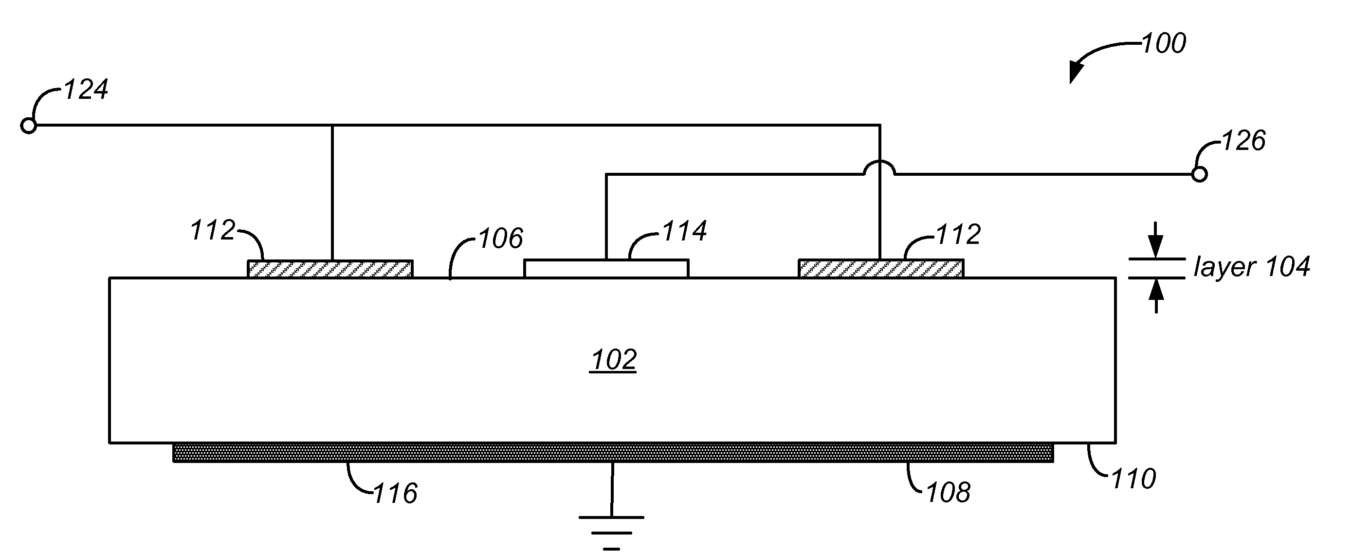
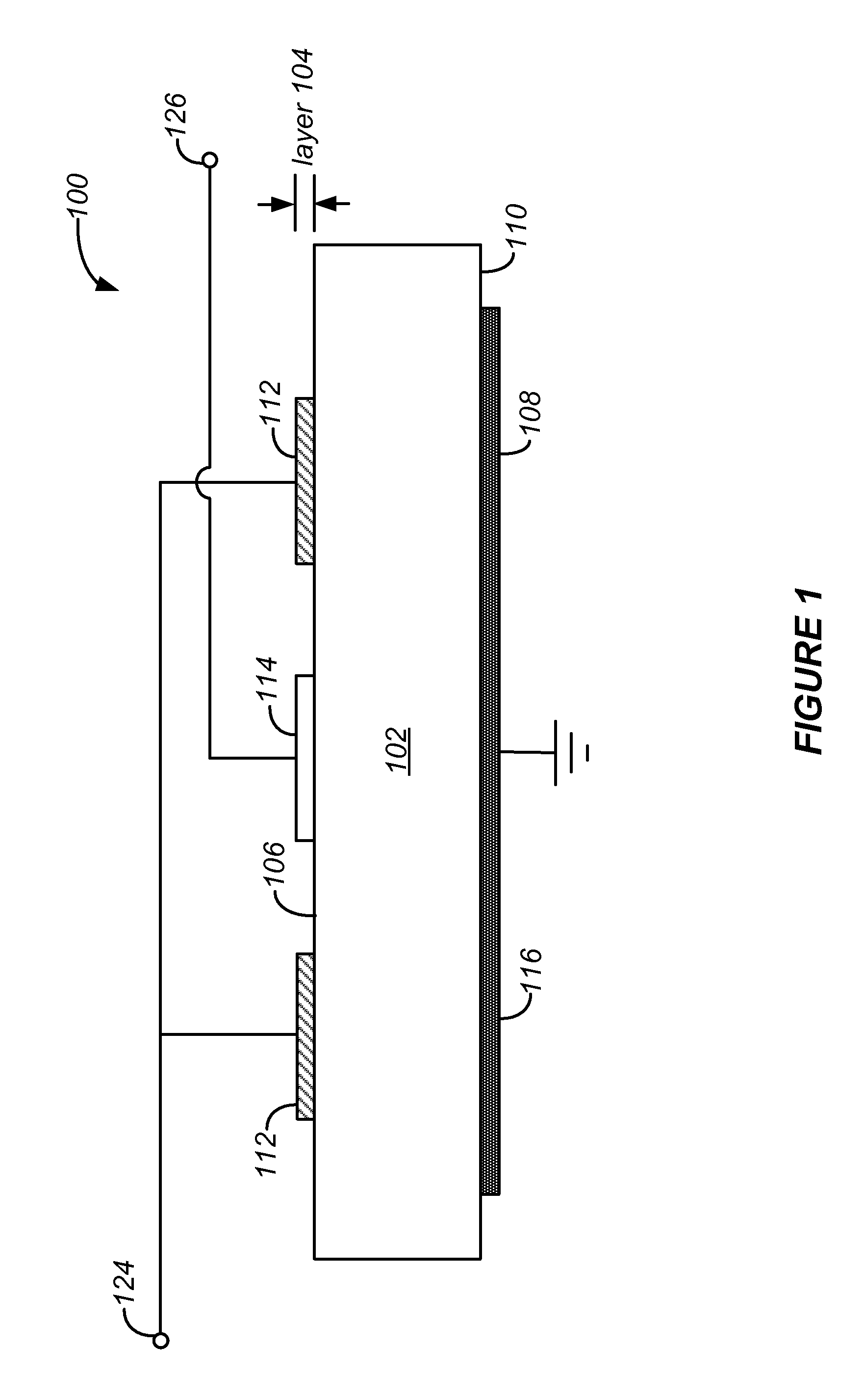
[0038]FIG. 1 illustrates a cross-sectional side view of an example piezoelectric transformer 100 that includes a piezoelectric layer 102, a first (upper)...


PUM

PropertyMeasurementUnit
Timeaaaaaaaaaa
Timeaaaaaaaaaa
Timeaaaaaaaaaa

Abstract

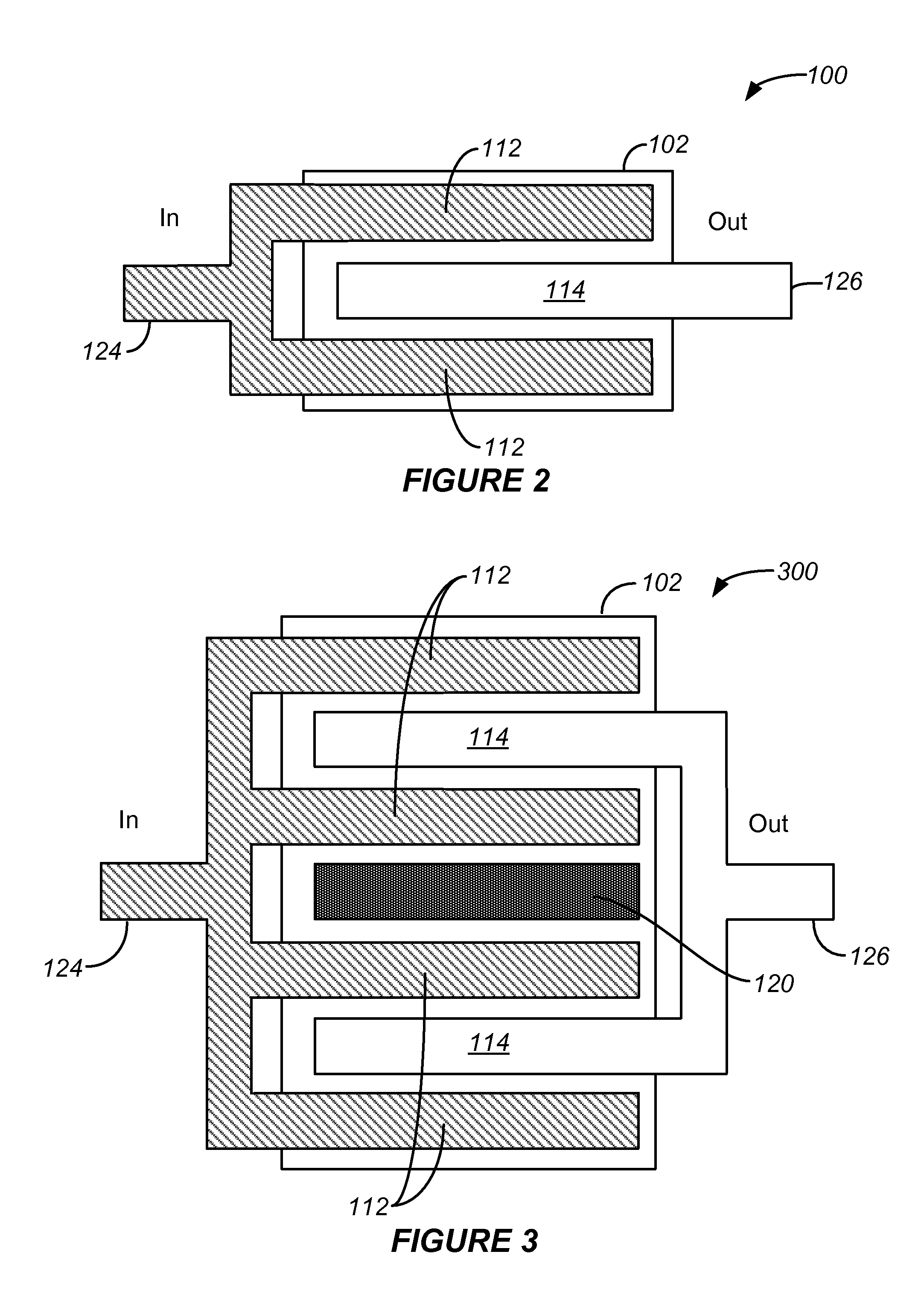
This disclosure provides implementations of electromechanical systems piezoelectric resonator transformers, devices, apparatus, systems, and related processes. In one aspect, a transformer includes a piezoelectric layer; a first conductive layer arranged over a first surface of the piezoelectric layer including a first set of electrodes and a second set of electrodes interdigitated with the first set. The transformer includes a second conductive layer arranged over a second surface including at least a third set of electrodes. In some implementations, the transformer includes a first port capable of receiving an input signal and to which the first set of electrodes are coupled, and a second port capable of being coupled to a load and of outputting an output signal, the second set of electrodes being coupled to the second port. Generally, a ratio of the number of electrodes of the second set to the first set characterizes a transformation ratio.

Description

TECHNICAL FIELD[0001]This disclosure relates generally to electromechanical systems (EMS) transformers, and more specifically to piezoelectric EMS resonators suitable for use as transformers.DESCRIPTION OF THE RELATED TECHNOLOGY[0002]Electromechanical systems (EMS) include devices having electrical and mechanical elements, transducers such as actuators and sensors, optical components (including mirrors), and electronics. Electromechanical systems can be manufactured at a variety of scales including, but not limited to, microscales and nanoscales. For example, microelectromechanical systems (MEMS) devices can include structures having sizes ranging from about one micron to hundreds of microns or more. Nanoelectromechanical systems (NEMS) devices can include structures having sizes smaller than one micron including, for example, sizes smaller than several hundred nanometers. Electromechanical elements may be created using deposition, etching, lithography, and / or other micromachining p...

Claims


Application Information

Patent Timeline
IPC IPC(8): H01L41/107H01L41/22
CPCH01L41/047H01L41/107Y10T29/42H03H9/02228H01L41/29H10N30/87H10N30/40
Inventor YUN, CHANGHAN HOBIELO, CHI SHUNZUO, CHENGJIEKIM, JONGHAE
Owner SNAPTRACK
Learn More