Ultrasonic transducer for use in a fluid medium

a transducer and ultrasonic technology, applied in the direction of instruments, liquid/fluent solid measurement, volume metering, etc., can solve the problems of insufficient robustness of materials, inability to easily suspend ultrasonic transducers in the housing, and inability to meet the requirements of ultrasonic echo times, etc., to achieve more accurate flow measurement, improve the damping of ultrasonic transducers, and improve the effect of the damping

Inactive Publication Date: 2013-05-30
ROBERT BOSCH GMBH
View PDF9 Cites 14 Cited by
  • Summary
  • Abstract
  • Description
  • Claims
  • Application Information

AI Technical Summary

Benefits of technology

[0008]Accordingly, an ultrasonic transducer and a method for manufacturing an ultrasonic transducer are provided, which eliminate the above-described disadvantages of known ultrasonic transducers. In particular, the present invention contributes towards providing improved damping of an ultrasonic transducer in such a manner, that structure-borne noise components are not necessarily limited with regard to their amplitude, but with regard to their emission time period, so that they are already decayed at the beginning of the receiving period for the actual useful signal. This allows more accurate measurement of the ultrasonic echo times and therefore, in turn, a more accurate flow measurement. However, as an alternative to, or in addition to, use in a flow measurement, the ultrasonic transducers of the exemplary embodiments and / or exemplary methods of the present invention may also be used for a multitude of other applications, for example, one or more of the above-mentioned applications. In particular, due to the excellent damping characteristics, the proposed ultrasonic transducers may be used in devices, which have at least two ultrasonic transducers that interact with each other. However, other set-ups are also theoretically feasible.
[0009]An ultrasonic transducer for use in a fluid medium, in particular, in a gas and / or in a liquid, is provided. This includes at least one housing and at least one transducer core at least partially accommodated in the housing. In this context, a housing is to be understood as an object, which has at least one interior chamber, for example, a hollow space, which is at least partially closed or, possibly, even partially open. The housing may be, for example, sleeve-shaped, in particular, at least substantially axially symmetric. The housing may achieve, in particular, the object of providing the ultrasonic transducer components accommodated in the interior chamber of the housing, with protection from mechanical and / or chemical influences. The housing may be made, for example, out of a plastic and / or a metallic material. However, ceramic housings are also theoretically feasible.
[0024]In particular, a casting process, for example, a vacuum casting process, may be used for introducing the damping material and / or the matrix material into the housing. In particular, a vacuum casting process may have the advantage that degassing of the damping material and / or the matrix material may take place simultaneously to and / or immediately prior to the introduction into the housing. The damping material and / or the matrix material may be gelled after the introduction into the housing.

Problems solved by technology

A general problem with this is suppressing parasitic ultrasonic paths, which run through the materials of the sensor housing to the transducer core, or in the reverse direction.
Such parasitic ultrasonic paths would otherwise distort the measuring signal, through which, for example, an ascertained value for the flow rate to be measured would often exceed a tolerance limit.
In particular, in the development of flow sensors for gases, based on the measurement of ultrasonic echo times, there is the general problem that even when an impedance-matching layer is used, as a rule, only relatively small ultrasonic amplitudes may be produced in the gas to be measured, which means that the structure-borne noise components, which are superimposed with the ultrasonic signals and are transmitted through the sensor housing, have a particularly critical effect.
On the other hand, in the presence of aggressive media, the ultrasonic transducers may not easily be suspended in the housing, decoupled from structure-borne noise by soft, and therefore, mostly not very robust materials.

Method used


Image

  • Ultrasonic transducer for use in a fluid medium
  • Ultrasonic transducer for use in a fluid medium
  • Ultrasonic transducer for use in a fluid medium

Examples


Embodiment Construction

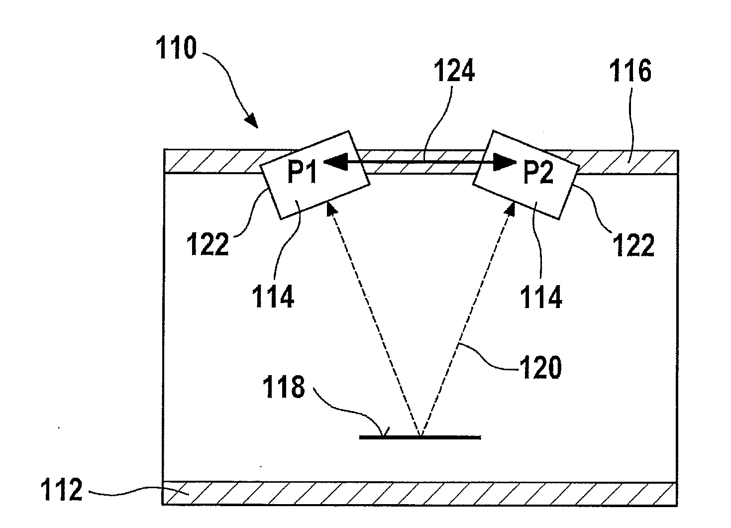
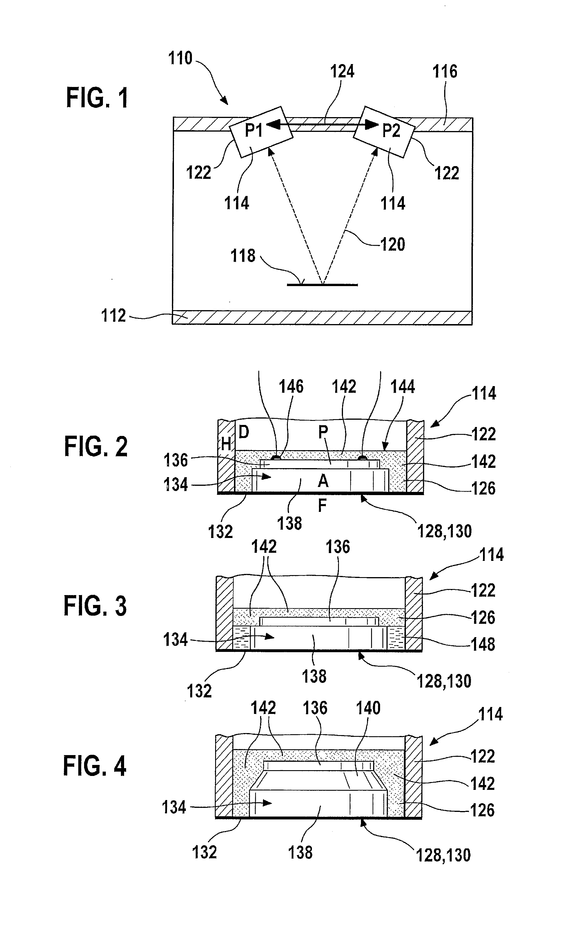
[0034]An exemplary embodiment of a sensor system 110, which may be used, for example, for determining flow characteristics of a fluid medium in a flow pipe 112, is represented in FIG. 1. In the exemplary embodiments illustrated, sensor system 110 includes two ultrasonic transducers 114, which are mounted in a pipe wall 116 of flow pipe 112, and which are denoted by P1 and P2 in FIG. 1. Sensor system 110 may be used, for example, for ascertaining a flow rate through flow pipe 112. The two ultrasonic transducers 114 (P1 and P2) mounted in an offset manner in the flow direction transmit ultrasonic pulses to each other directly or, as illustrated in FIG. 1, via a reflecting surface 118. This desired signal propagation of the ultrasonic signals is also referred to as a useful signal path 120 and is illustrated in FIG. 1 by a dashed line. In addition, structure-borne noise is transmitted between the two ultrasonic transducers 114 via pipe wall 116 and / or via housings 122 of ultrasonic tra...


PUM

PropertyMeasurementUnit
sizeaaaaaaaaaa
particle sizeaaaaaaaaaa
sizeaaaaaaaaaa

Abstract

An ultrasonic transducer for use in a fluid medium. The ultrasonic transducer includes at least one housing and at least one transducer core at least partially accommodated in the housing. The transducer core includes at least one acoustic-electric transducer element. At least one damping material is also accommodated in the housing. The damping material includes at least one matrix material, at least one first filler introduced into the matrix material, and at least one second filler introduced into the matrix material. The first filler has a lower specific gravity than the matrix material. The second filler has a higher specific gravity than the matrix material.

Description

FIELD OF THE INVENTION[0001]The present invention relates to an ultrasonic transducer for use in a fluid medium.BACKGROUND INFORMATION[0002]Ultrasonic transducers for various areas of application are believed to be in the related art. Thus, ultrasonic transducers are used, for example, in fluid media such as gases and / or liquids, in order to measure a fluid level and / or a flow characteristic, such as a mass flow rate or volumetric flow rate or a speed of the fluid medium. In particular, such ultrasonic transducers are used in the induction and / or exhaust tract of internal combustion engines. Alternatively, or in addition, ultrasonic transducers may also be used, for example, as distance sensors in air or other gases or liquids.[0003]Ultrasonic transducers have, as a rule, at least one electroacoustic transducer element, for example, a piezoelectric transducer element, which is configured to convert electrical signals into ultrasonic signals or vice versa. Thus, ultrasonic transducer...

Claims


Application Information

Patent Timeline
Patent Type & Authority Applications(United States)
IPC IPC(8): G01N29/02
CPCG01F1/662G01F15/006Y10T29/49005G01N29/02G10K11/002
Inventor LANG, TOBIAS
Owner ROBERT BOSCH GMBH
Why Eureka
Try Eureka