Liquid crystal display and method for preparation thereof
a technology of liquid crystal display and liquid crystal, which is applied in the manufacture of electrode systems, electric discharge tubes/lamps, instruments, etc., can solve the problems of poor transmission rate and slow response time, drawback of narrow viewing angle, and higher rotational viscosity, and achieves high contrast ratio, wide viewing, and low driving and threshold voltage
- Summary
- Abstract
- Description
- Claims
- Application Information
AI Technical Summary
Benefits of technology
Problems solved by technology
Method used
Image
Examples
first embodiment
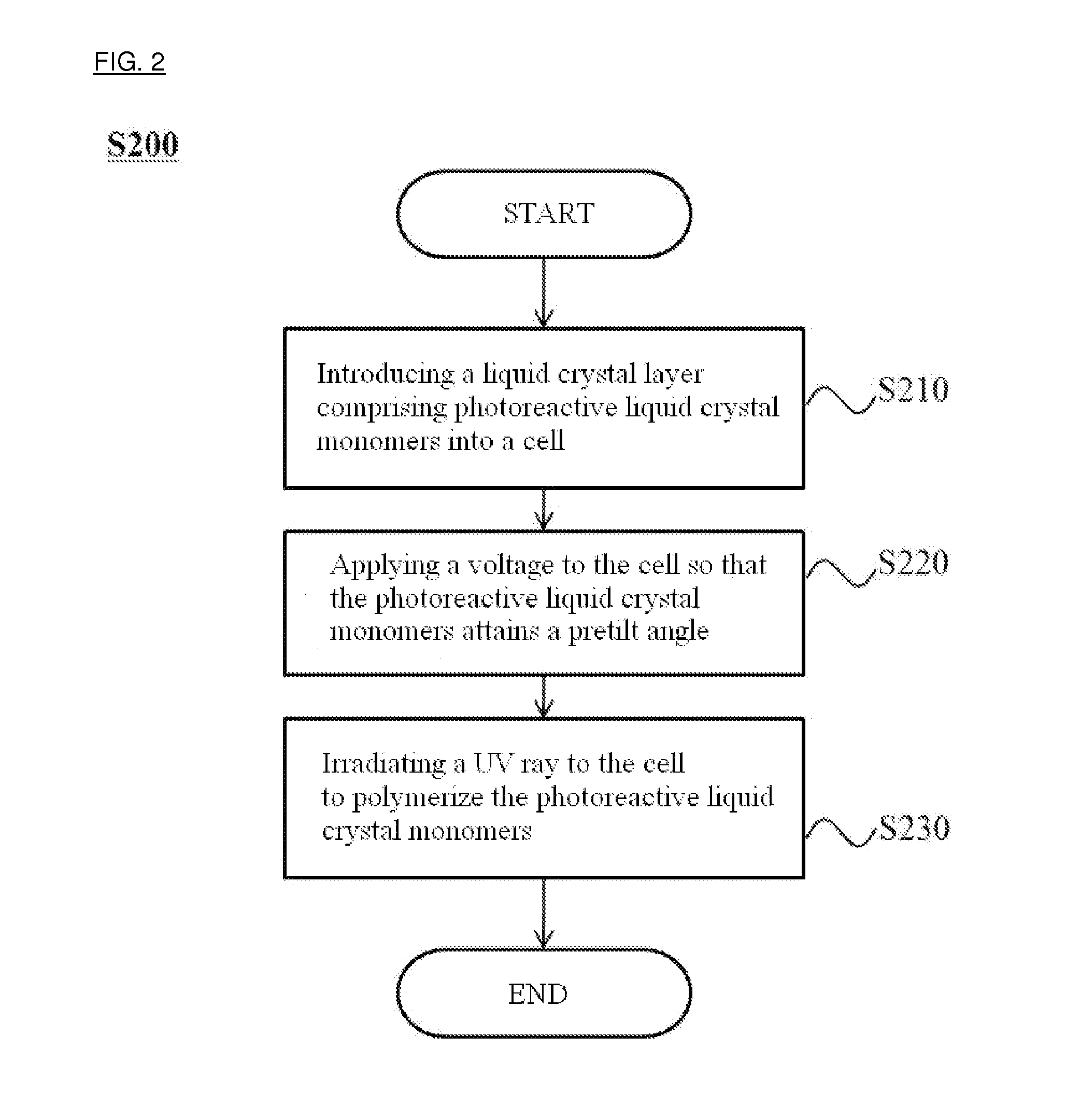
[0056]FIG. 2 is a flow diagram showing the process of preparing the liquid crystal display according to another embodiment. FIG. 3 is a sectional view of the liquid crystal display prepared by the method according to the
[0057]Referring to FIG. 2, a method for forming a pretilt angel of a photoreactive liquid crystal monomer of the liquid crystal display according to the other embodiment (200) comprises the steps of: introducing a liquid crystal layer mixed with a photoreactive liquid crystal monomer into a cell (S210); applying a voltage thereto to form a constant pretilt angle on the photoreactive liquid crystal monomers (S220); and irradiating a UV ray to polymerize the photoreactive liquid crystal monomers (S230).
[0058]First, in the step of introducing a liquid crystal layer mixed with photoreactive liquid crystal monomers into a cell (S210), the liquid crystal may be of initial positive dielectric anisotropy as described above for fast response time, and it may be one or more se...
second embodiment
[0065]FIG. 4a and FIG. 4b are sectional views of the liquid crystal display when voltage is applied or not applied, respectively.
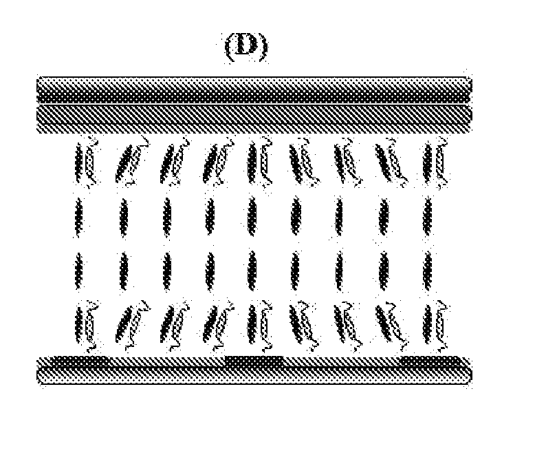
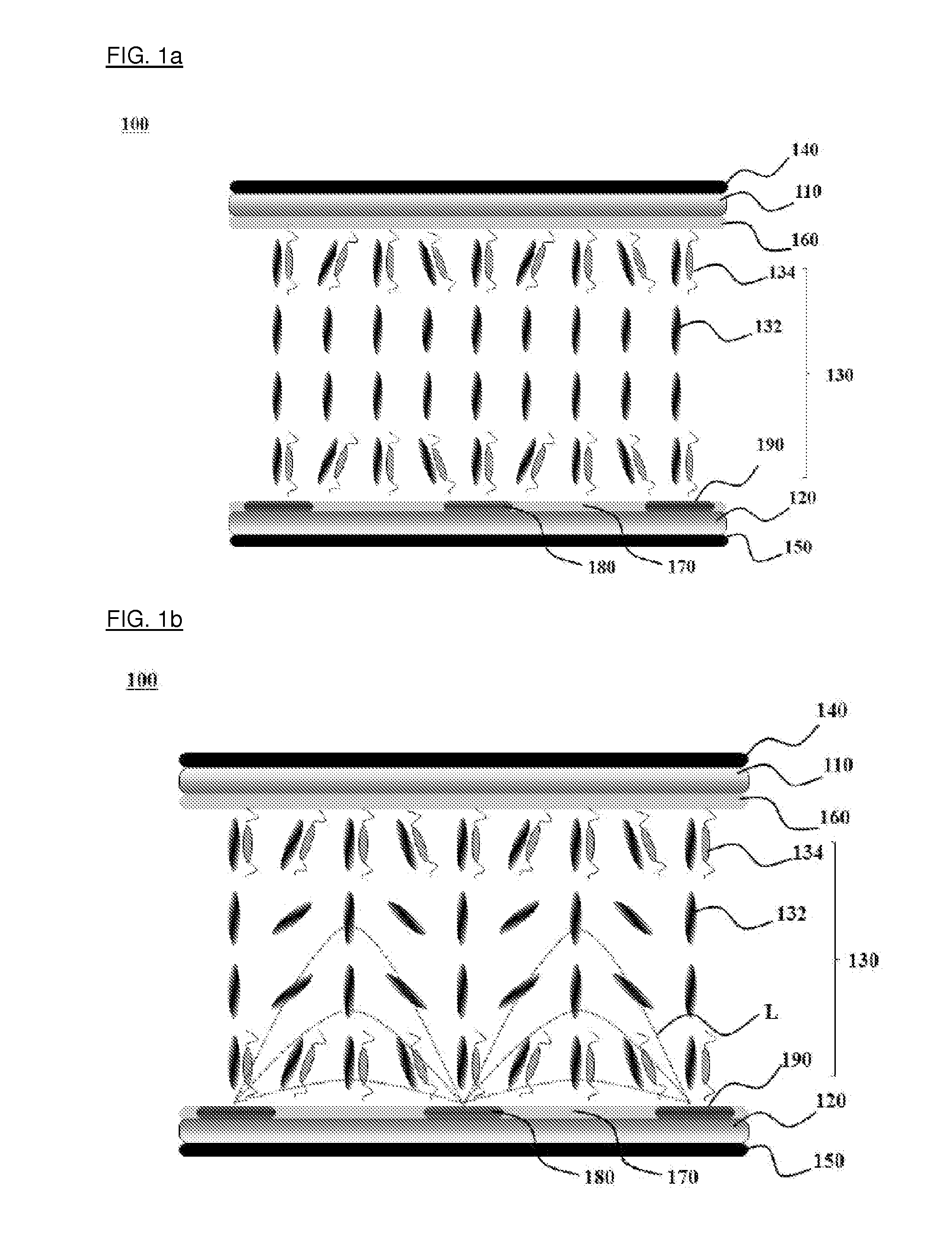
[0066]Referring to FIGS. 4a and 4b, the liquid crystal display (200) according to the second embodiment comprises a first substrate (210) and the second substrate (220) which are aligned parallel with each other, and a liquid crystal layer (230) which is positioned between the first substrate (210) and the second substrate (220), wherein the first substrate (210) and the second substrate (220) respectively comprise a first vertical alignment layer (260) and a second vertical alignment layer (270) toward the liquid crystal layer (230), and the second substrate (220) contains two common electrode (280, also referred to “the first pixel electrode”) and pixel electrode (290, also referred to “the second pixel electrode”). This display is identical to the liquid crystal display (100) according to the first embodiment described by reference to FIGS. 1a and 1b, ...
third embodiment
[0078]FIGS. 6a and 6b are cross-sectional drawings of the LCD when applied voltage is on and off, respectively.
[0079]Referring to FIGS. 6a and 6b, an LCD (300) according to the third embodiment is the same as the LCD (100) according to the first embodiment as well as the LCD (200) according to the second embodiment in that it comprises the first board (310) and the second board (320) which face each other and a liquid crystal layer (330) disposed between the first board (310) and the second board (320). The first board (310) and the second board (320) comprise the first vertical alignment layer (360) and the second vertical alignment layer (370) vertically aligned with respect to the direction of the liquid crystal layer (330), and the second board (320) comprises two common electrodes (380) and a pixel electrode (390).
[0080]The LCD (300) according to the third embodiment is different from the LCD (100) according to the first embodiment or the LCD (200) according to the second embo...
PUM
| Property | Measurement | Unit |
|---|---|---|
| pretilt angle | aaaaa | aaaaa |
| pretilt angle | aaaaa | aaaaa |
| pretilt angle | aaaaa | aaaaa |
Abstract
Description
Claims
Application Information
 - R&D
- Intellectual Property
- Life Sciences
- Materials
- Tech Scout
- Unparalleled Data Quality
- Higher Quality Content
- 60% Fewer Hallucinations
Browse by: Latest US Patents, China's latest patents, Technical Efficacy Thesaurus, Application Domain, Technology Topic, Popular Technical Reports.
© 2025 PatSnap. All rights reserved.Legal|Privacy policy|Modern Slavery Act Transparency Statement|Sitemap|About US| Contact US: help@patsnap.com


