
Method and device using plasmon- resonating nanoparticles

a technology of plasmon resonance and nanoparticles, which is applied in the direction of physical/chemical process catalysts, cell components, metal/metal-oxide/metal-hydroxide catalysts, etc., can solve the problems of inherently difficult fine control, extremely energy-intensive thermochemical processes, etc., and achieve the effect of efficient us

Inactive Publication Date: 2013-05-16
RGT UNIV OF MICHIGAN
View PDF4 Cites 15 Cited by
  • Summary
  • Abstract
  • Description
  • Claims
  • Application Information

AI Technical Summary

Benefits of technology

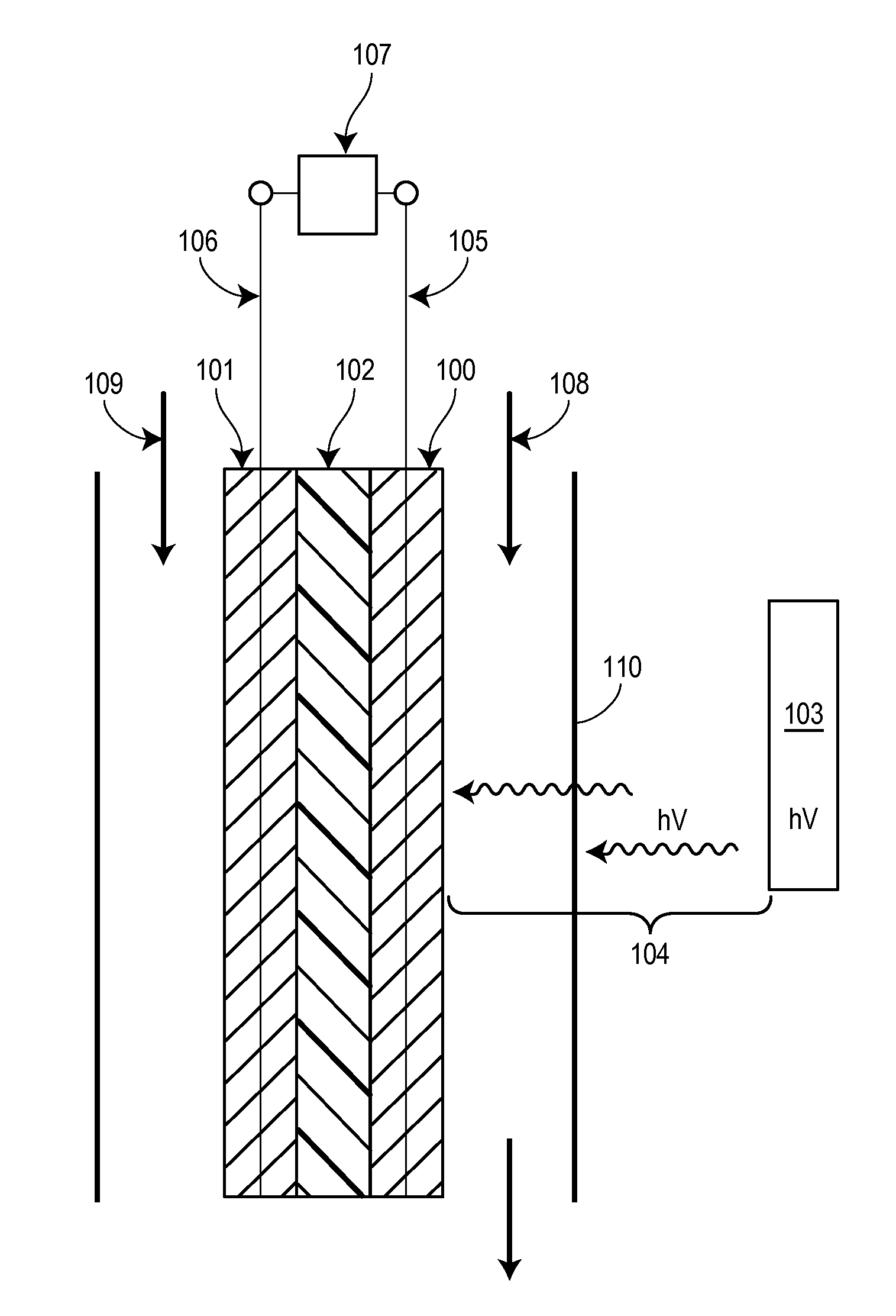
This patent describes a new method and device that uses a special type of nanoparticle called a plasmon-resonating nanostructure to reduce an oxidant using a photo-thermal mechanism. This process can be highly efficient and can be used in various applications like fuel cells or catalytic reactors. The method involves exposing the nanostructure to photons and reducing the oxidant at a faster rate compared to the same conditions without the photons. The device used in this method includes a plasmon-resonating nanostructure made of copper, silver, gold or their alloys. This technology has potential to be a useful tool in chemical research and development, and can have significant implications in various fields like electronics, sensors, and energy production.

Problems solved by technology

Despite their wide acceptance, thermochemical processes, commonly run at temperatures between about 200° C. to about 800° C., are extremely energy intensive, and are inherently difficult to finely control.
For example, the design of optimal catalytic materials is hampered by the materials often changing size and / or shape upon heat which effects the catalytic activity / selectivity at high temperatures.
Photocatalytic processes are typically less industrially applicable and almost exclusively require semiconducting materials.
These requirements are difficult to meet and, therefore, these materials are not considered to be sufficiently industrially versatile.
Despite the breadth of knowledge on the thermochemical processes, the prior art does not teach heterogeneous thermochemical catalytic processes promoted by photoexcitation (herein, photo-thermal catalysis).
Moreover, the prior art fails to teach catalytic materials that combine thermocatalytic capabilities of metal catalysts with photochemical excitation.

Method used


Image

  • Method and device using plasmon- resonating nanoparticles
  • Method and device using plasmon- resonating nanoparticles
  • Method and device using plasmon- resonating nanoparticles

Examples


example 1

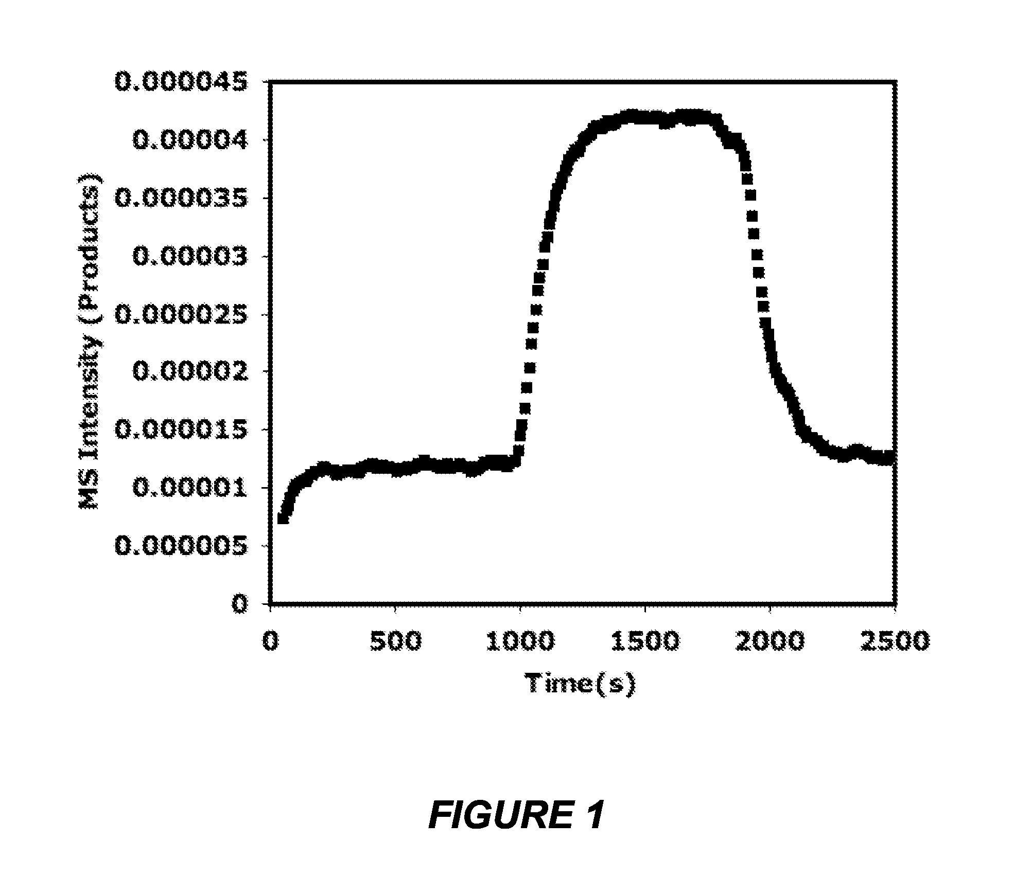
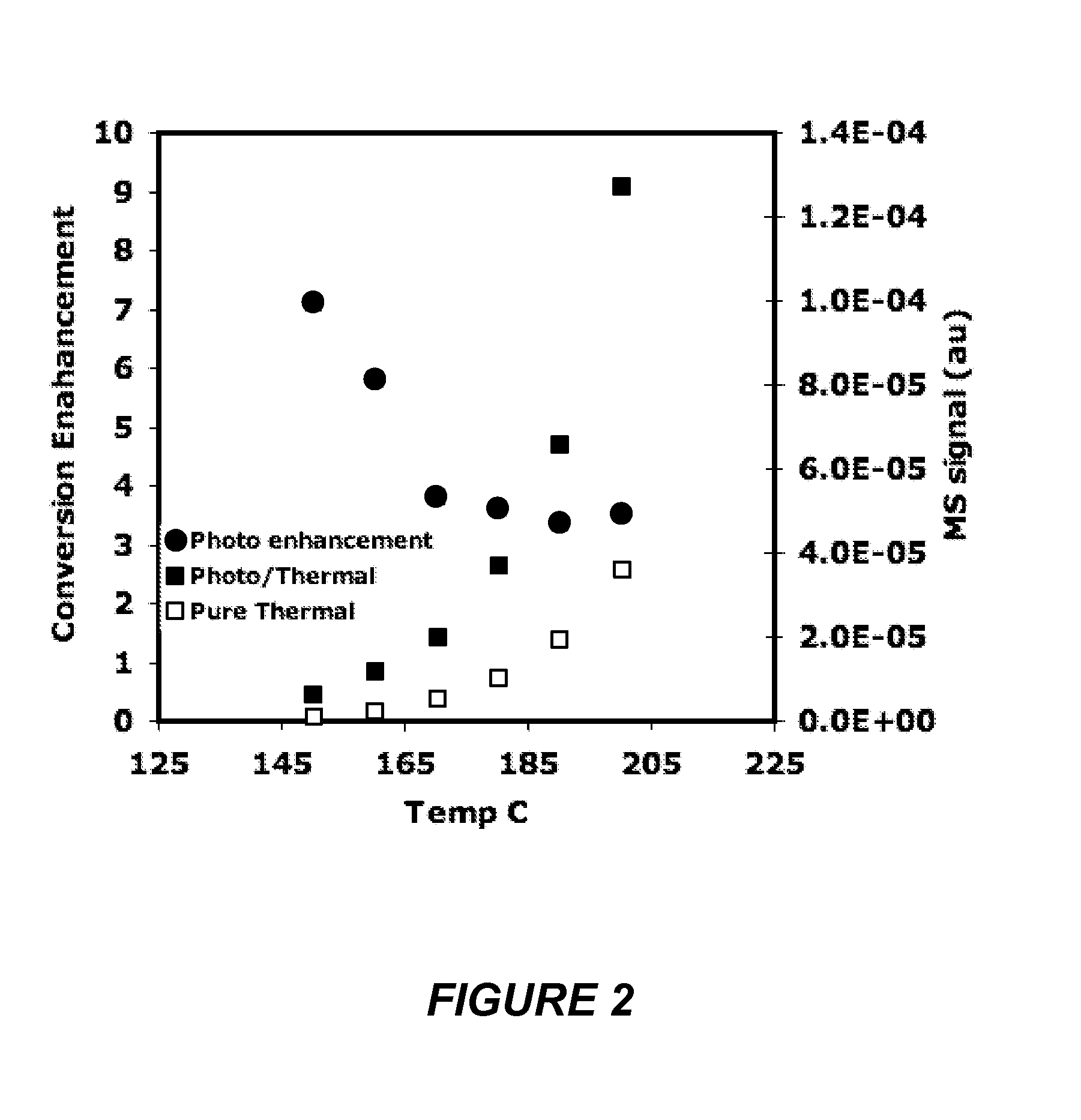
[0077]Initial temperature dependent photothermal experiments were conducted to examine the effect of visible light illumination on the activity and selectivity for the ethylene epoxidation reaction, CO oxidation reaction and NH3 oxidation reactions. At each temperature the catalyst was allowed 15 minutes to reach steady state under dark conditions followed by 15 minutes of visible light illumination, followed by 15 minutes in the dark to assure that the activity returned back to the initial dark baseline. The enhancement is calculated as the total rate under visible light illumination divided by the pure thermocatalytic rate with no illumination. In the case of ethylene epoxidation, the selectivity to ethylene oxide as well as the ethylene oxide yield as a function of temperature is also examined. The visible source used in all the experiments is a broad band white light source with an intensity of 50 mW / cm2 and a maximum output at 580 nm.

[0078]Ethylene epoxidation:

C2H4+½O2→C2H4O (E...

example 2

Intensity And Wavelength Dependence Of Ethylene Epoxidation Over Silver

Intensity Dependent Photothermal Tests

[0084]The mechanism of photocatalytic rate enhancement and the effect of source intensity on the photo-enhancement were examined by intensity dependent experiments. The intensity was varied by controlling the power input to the source but also could have been controlled by filters or other means. FIG. 25(b) indicates a direct (linear) correlation between the photocatalytic activity and the source intensity up to 250 mW / cm2. This linear dependence on source intensity is indicative of an electron driven process. FIG. 26 shows the rate of ethylene epoxidation over silver nanocrystals vs. incident photon intensity as a function of reactor temperature. Unlike FIG. 25(b), the high intensity photo-catalytic process is indicative of a multi-electron driven process. FIG. 26 shows the conversion efficiencies for ethylene to ethylene oxide as a function of temperature for different inci...

example 3

Isotopic Labeling Experiments

[0090]The mechanism of photocatalytic activity was examined by monitoring the effect of labeled 18O on the pure thermal and photothermal catalytic reactions. 18O was introduced for 10-15 minutes to allow the system to reach steady state and the quantity of 18O based products (m / z 46 and 48) were monitored. FIG. 25(c) shows the results of the effect of switching from 16O2 (at least 99% 16O2) to 18O2 (at least 99% 18O2) in the photo-thermal ethylene epoxidation with a silver catalyst; a 16% decrease in reaction rate. This comparison the isotopic effect for the analogous thermal process showed a 5% decrease in reaction rate when 18O2 was used.

[0091]We believe the enhancement mechanism is similar to one that has been previously found to play a role in femtosecond laser induced desorption / reaction experiments on metallic surfaces is the hot electron induced population of unpopulated adsorbate antibonding orbitals. Femtosecond laser induced photochemistry expe...


PUM

PropertyMeasurementUnit
temperatureaaaaaaaaaa
temperaturesaaaaaaaaaa
temperatureaaaaaaaaaa

Abstract

Disclosed herein are methods and articles that include a plasmon-resonating nanostructure that employ a photo-thermal mechanism to catalyze the reduction of an oxidant. As such, the plasmon-resonating nanostructure catalyzes a redox reaction at a temperature below a predetermined activation temperature. The method can be efficiently used to catalyze the reduction of an oxidant, for example in a catalytic reactor or in a fuel cell that includes a photon source.

Description

CROSS-REFERENCE TO RELATED APPLICATION[0001]The benefit of priority under 35 USC §119(e) of U.S. provisional patent application Ser. No. 61 / 346,771 filed May 20, 2010, the disclosure of which is incorporated herein by reference, is claimed.STATEMENT OF GOVERNMENT INTEREST[0002]This invention was made with governmental support under grants from the U.S. Department of Energy, Office of Basic Energy Sciences (DOE-BES) and Division of Chemical Science (FG-02-05ER15686), and the National Science Foundation (CBET 0756255). The government has certain rights in the invention.BACKGROUND[0003]Industrial heteroegeneous catalytic processes are almost exclusively thermally activated. The catalytic process is driven by overcoming activation barriers or shifting equilibria by raising the temperature of the heterogeneous catalyst. The activation temperature of the catalytic process is typically the temperature necessary to overcome the highest activation barrier. These thermochemical processes are ...

Claims


Application Information

Patent Timeline
Patent Type & Authority Applications(United States)
IPC IPC(8): B01J19/12H01M4/86C07D301/08C01B31/20C01B21/36H01M8/10C07D301/10C01B32/50
CPCB01J19/0093H01M14/005B01J23/72B01J35/0013B01J35/004B01J35/1009B01J35/1019B01J37/009B01J37/0211B01J2219/00783B01J2219/00828B01J2219/00831B01J2219/00835B01J2219/00846B01J2219/0086B01J2219/00943B01J19/122C01B21/36C01B31/20C07D301/08C07D301/10H01M4/86H01M8/10Y02E60/523H01M8/1002H01M8/1011H01M4/9041H01M4/925B01J23/50H01M8/1007C01B32/50Y02E60/50B01J35/612B01J35/615B01J35/39B01J35/45B01J35/23
Inventor LINIC, SULJOCHRISTOPHER, PHILLIP N.
Owner RGT UNIV OF MICHIGAN
Learn More