
Filling device having a flow regulation system

a technology of flow regulation and filling device, which is applied in the direction of packaging, transportation and packaging, liquid handling, etc., can solve problems such as flow turbulence, and achieve the effect of simple design and implementation

Active Publication Date: 2013-05-09
HEMA
View PDF34 Cites 6 Cited by
  • Summary
  • Abstract
  • Description
  • Claims
  • Application Information

AI Technical Summary

Benefits of technology

[0007]The purpose of this invention is to propose a solution aiming to overcome at least one of the aforementioned disadvantages, which is simple in design and implementation.

Problems solved by technology

This restriction of the passage creates turbulences in the flow.

Method used


Image

  • Filling device having a flow regulation system
  • Filling device having a flow regulation system
  • Filling device having a flow regulation system

Examples


first embodiment

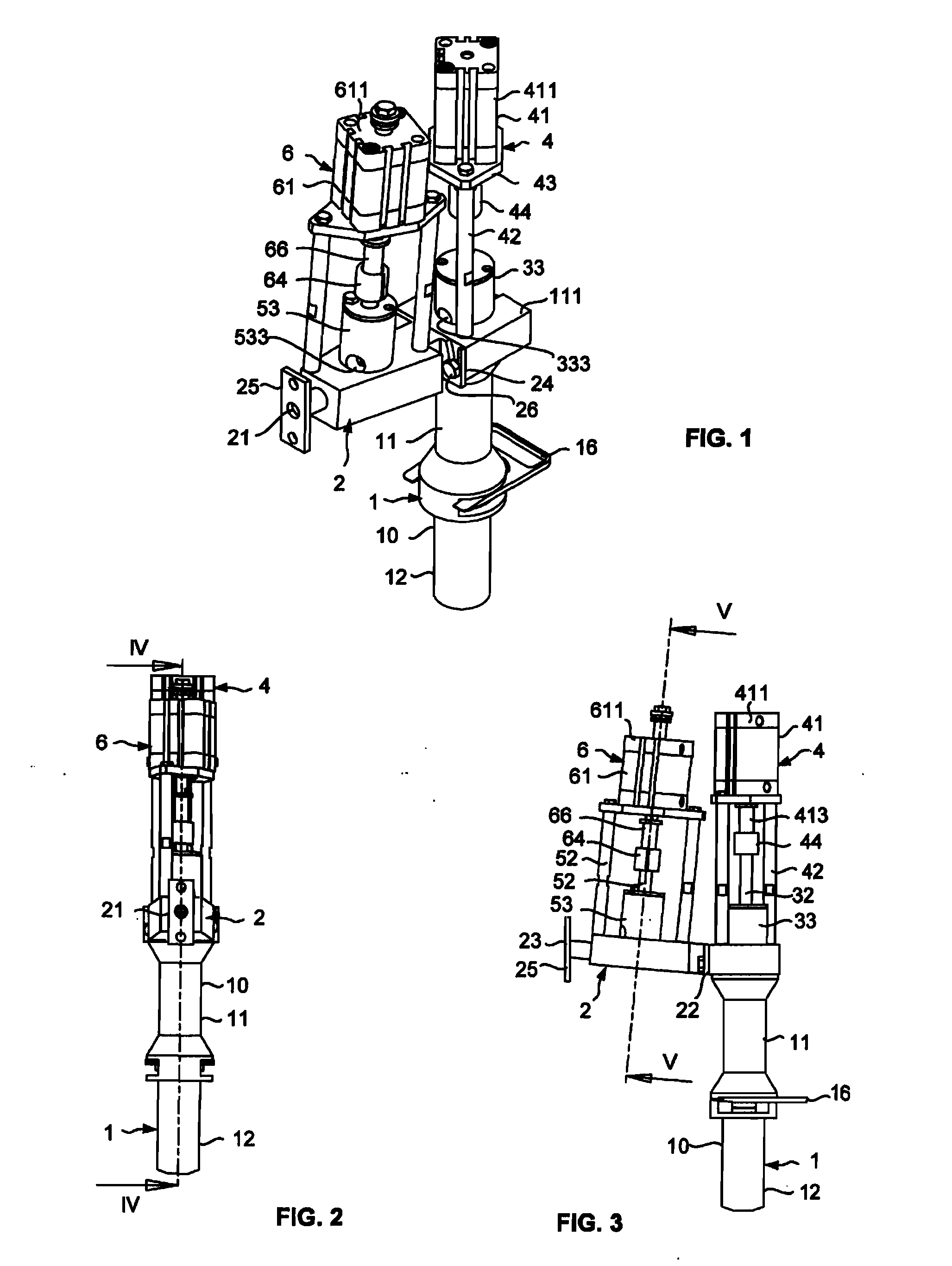
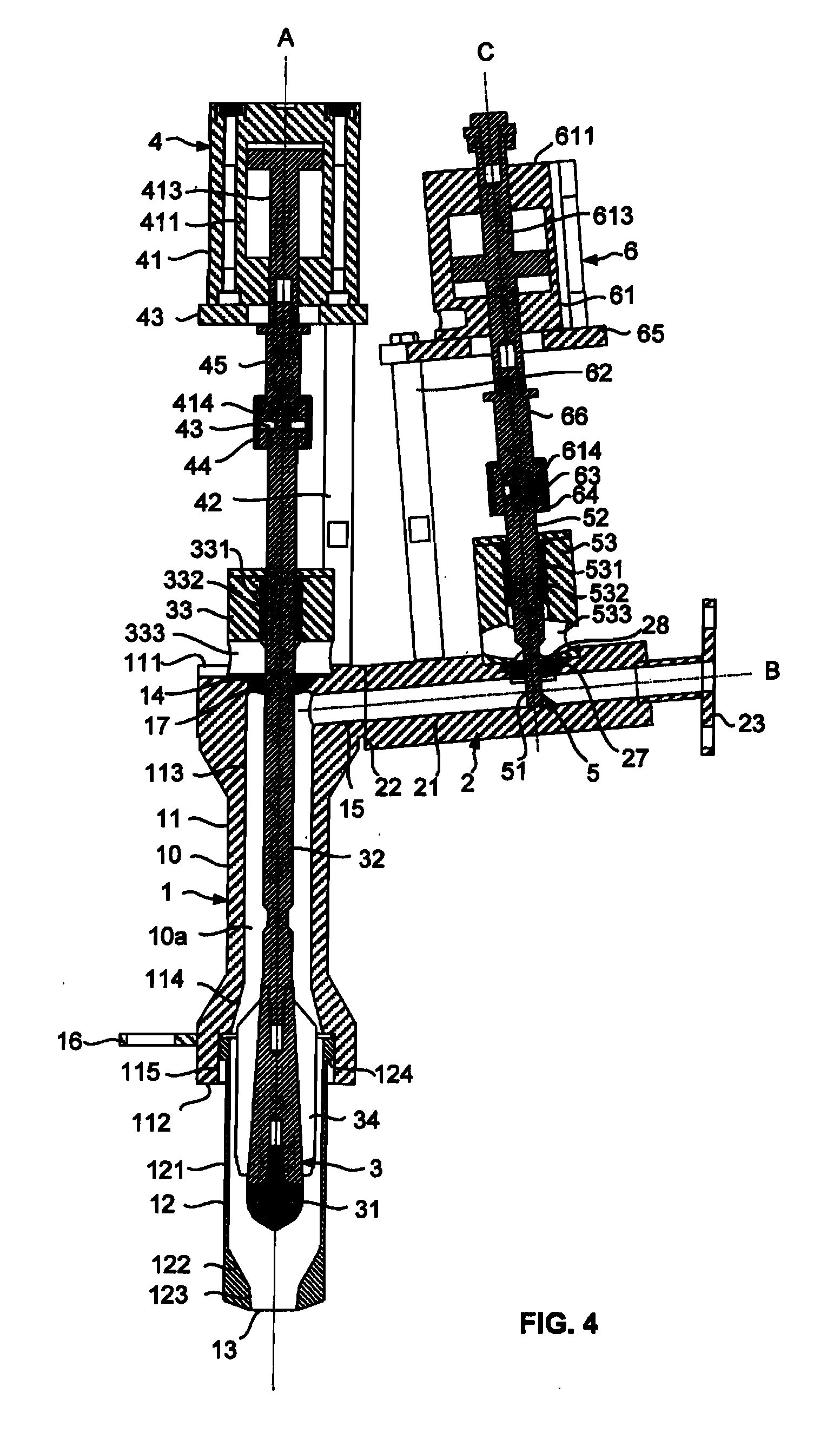
[0058]FIGS. 1 to 6 show a filling device according to the invention, intended to be provided for a machine for filling, for example of the rotary type, comprising a carrousel comprising a support structure mounted rotating about a fixed frame around a vertical axis of rotation. The support structure carries dispensing means filling liquid, formed for example of a cylindrical central tank, and a plurality of filling devices according to the invention, located at regular angular intervals around the axis of rotation.

[0059]The filling device can be used for liquid filling products, such as water, milk, fruit juices or detergents, whether or not comprising pulps, to semi-liquids, such as drinkable yoghurt, sauces, vegetable oil or washing powder. The device shown in the figures is in particular intended to be used for the dosing of milk.

[0060]In reference in particular to FIGS. 1 and 4, the filling device comprises a filling spout 1 with an outlet orifice 13 and a lateral feed orifice 1...

second embodiment

[0079]FIGS. 7 to 13 show a filling device according to the invention.

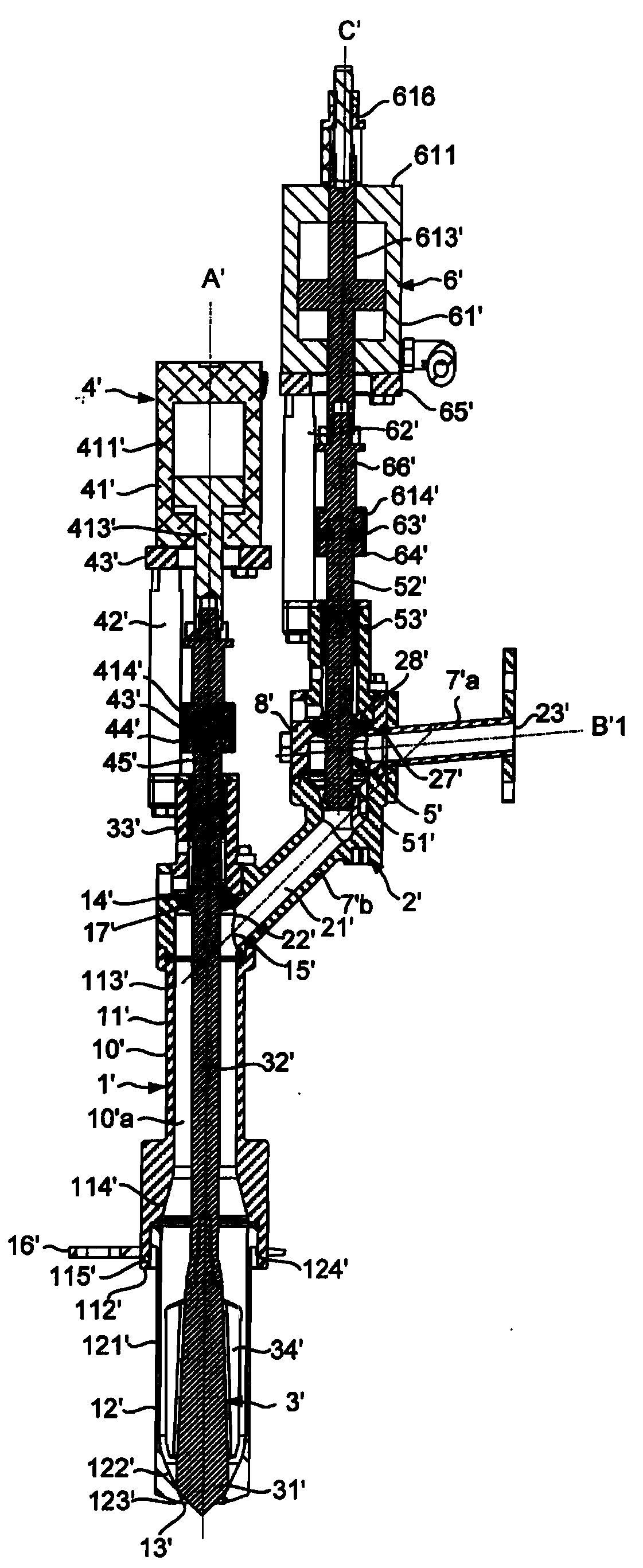
[0080]In reference in particular to FIGS. 7 and 10, the filling device comprises a filling spout 1′ with an outlet orifice 13′ and a lateral feed orifice 15′, a feed duct 2′ connected to the feed orifice 15′ for supplying the spout with filling product, and dosing means in order to deliver a determined quantity of filling product into each container brought under the spout.

[0081]The spout 1′, with longitudinal axis A′, is formed by a globally tubular body 10′ having an internal passage 10′a, an open upper axial end 14′ and an open lower axial end constituting the outlet orifice 13′. The longitudinal axis A′ of the spout is arranged substantially vertically.

[0082]The feed duct 2′ has an internal passage 21′ and is connected by a first end 22′ to the feed orifice. The filling device is intended to be connected by the second end 23′ of the feed duct to the tank of the machine for filling.

[0083]The tubular body 10′ com...


PUM


Abstract

A filling device for a machine for filling containers, includes a spout having an outlet orifice and a feed orifice, and a feed duct connected to the feed orifice. A first actuating system is able to move a valve, which is mounted in the spout, between a closed position for closing the outlet orifice and at least one open position. A flow-regulating rod is mounted in a sliding manner in a hole in the feed duct and is able to be moved by a second actuating system between a high flow-rate position, in which the rod is located substantially outside the internal passage in the feed duct, and a low flow-rate position, in which the rod extends into the internal passage in order to reduce the passage cross section of the feed duct.

Description

BACKGROUND[0001]This invention relates to a filling device for a machine for filling containers with a filling product, in particular a food product, as well as a corresponding machine for filling. This invention relates more particularly to a filling device provided with a flow regulation system for the filling of containers, such as bottles or jars, with any sort of products, liquid to viscous, in particular with products that tend to foam and / or products that contain particles and / or pieces.[0002]Machines for filling are known, in particular of the rotary type, comprising a rotating carrousel with a support structure carrying a tank of filling product and a plurality of filling devices. Each filling device conventionally comprises a filling spout, or dosing spout, a feed duct connecting the tank to the filling spout in order to feed the filling spout with filling product, and dosing means in order to deliver a determined quantity of filling product into each container brought und...

Claims


Application Information

Patent Timeline
Patent Type & Authority Applications(United States)
IPC IPC(8): B67C3/28
CPCB67C3/28B67C3/286
Inventor HUITOREL, MICKAELPASQUET, ARNAUDCADIOU, DIDIER
Owner HEMA
Learn More