Sensor

Inactive Publication Date: 2013-05-09
PUDAS MARKO
View PDF11 Cites 17 Cited by
  • Summary
  • Abstract
  • Description
  • Claims
  • Application Information

AI Technical Summary

Benefits of technology

The present invention is a sensor structure that can detect acceleration and related incidents such as drops, shocks, impacts etc. It can also verify the authenticity of an incident causing a permanent change by analyzing the stored data and / or the induced physical reconfiguration. The sensor structure is small in size and affordable. It can be used in various target objects such as logistic containers or electronic appliances, e.g. consumer electronics, to monitor their integrity, self-checks, detect flaws in structure and functioning, and verify the occurrence of at least a severe incident. The sensor structure can also be used in EVs as a fuse to cut power from an energy supply on an impact.

Problems solved by technology

However, in terms of costs, size and data verification, the contemporary solutions are far from perfect, if considered even adequate in the first place.
Namely, adding current condition monitoring equipment to target objects is both too expensive and space-consuming particularly in case the only purpose thereof is to measure and store indications of predetermined conditions of the object for future evaluation in connection with product warranty-related disputes, for example.
Secondly, with the present solutions the actual verification of condition monitoring data may be tricky as computer-based data storage arrangements and data associated therewith can be rather easily tampered with, whereupon questioning the validity of such data is in many scenarios somewhat justified.
Glass capillaries that are configured to break upon an impact of predetermined intensity may be utilized for detecting and particularly substantiating afterwards an occurrence of such incident, but they are typically large and clumsy, costly and omit electrical readability, which is also a major defect in modern day's electric society and environment.

Method used


Image

  • Sensor
  • Sensor
  • Sensor

Examples


Embodiment Construction

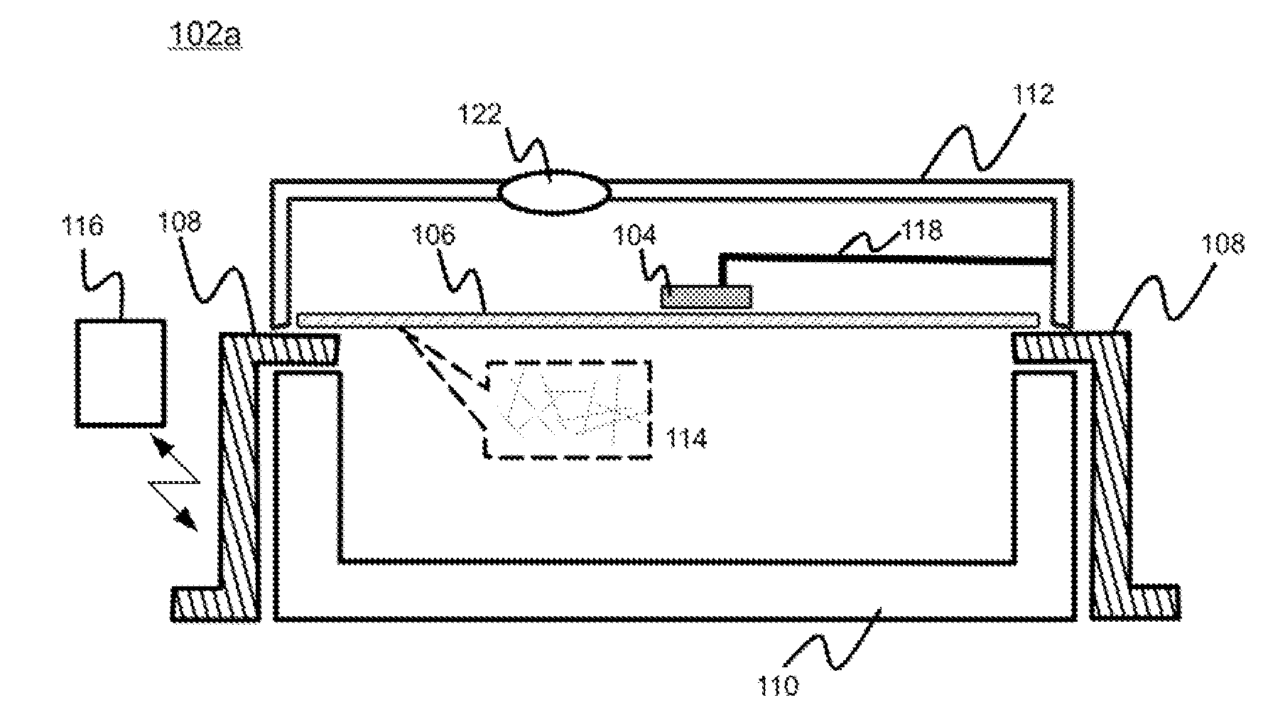
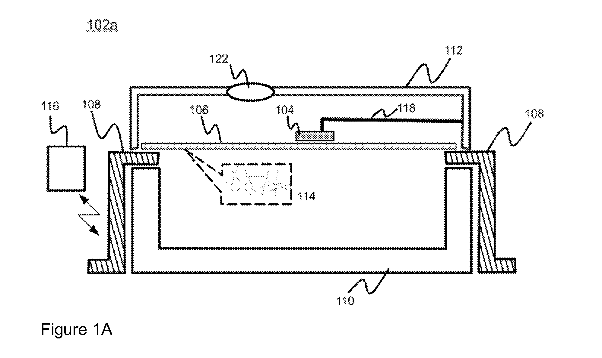
[0050]FIG. 1A discloses at 102a, representing a cross-sectional side view, an exemplary embodiment of the sensor structure feasible for coupling to or even inclusion in a target object such as an electronic device or a logistic container.

[0051]The support element in the form of a nanotube film, preferably a CNT freestanding film 106 is functionally coupled to the electric conductors 108, such as electrodes, from the edges or edge areas along the whole circumference or at least from a number of selected points such as two optionally opposing points in such a way, that the film 106 is suspended in the air or any other medium in between two electrodes. Preferably two electrical connections are utilized; however, at least one electrical connection ought to be present. Optical connectors, such as optical wave guides, may be utilized as well. Said electrodes are in turn being supported by carrier element(s) 110 Carrier elements 110 may be provided by casing, body, frame or other supportiv...


PUM


Abstract

A sensor structure includes a mass element (104, 204) and a support element (106, 206) for the mass element, either or both of the elements including carbon nanostructures (106, 114, 206) at least some of which are mutually non-parallel, the mass element and support element being configured such that upon acceleration or other mechanical or energy impact exceeding a predetermined threshold, a permanent change takes place in the physical configuration of the carbon nanostructures and in a dependent, measurable value of a predetermined electrical parameter, the electrical parameter optionally including or indicating at least one electrical property selected from the group consisting of: resistance, inductance, capacitance and impedance.

Description

FIELD OF THE INVENTION[0001]Generally the present invention pertains to sensors. In particular, however not exclusively, embodiments of the present invention concern impact and acceleration sensors advantageously capable of fuse-like performance, wherein the permanent change in measurable value occurs over the influence of external factors.BACKGROUND[0002]Product storage, transport and use conditions are of general concern regarding e.g. different liability and product warranty issues in various fields of trade and technology, such as medical equipment, for example. Monitoring of conditions such as temperature, humidity, radiation, speed and acceleration may be nowadays executed using available data gathering solutions typically incorporating a number of application-specific sensors, data processing equipment, data storage facilities and data transfer gear. From the purely technical standpoint data acquisition and transmission is thus not an especially complex task anymore as more p...

Claims


Application Information

Patent Timeline
IPC IPC(8): G01P15/00
CPCB82Y15/00G01P15/0891G01P15/06G01P15/08
Inventor PUDAS, MARKO
Owner PUDAS MARKO
Why Eureka
Try Eureka