
Hybrid wind and solar energy device

a solar energy and hybrid technology, applied in the field of renewable energy, can solve the problems of inefficient electricity generation methods, long time for recouping initial investment costs, and significant up-front costs, and achieve the effect of increasing efficiency and minimising environmental impa

Inactive Publication Date: 2013-05-02
BRYSON THOMAS PATRICK
View PDF2 Cites 34 Cited by
  • Summary
  • Abstract
  • Description
  • Claims
  • Application Information

AI Technical Summary

Benefits of technology

The patent is about a new energy device that can produce work with minimal environmental impact. It is made up of a rotating solar panel and wind turbine that work together to increase efficiency. The device is easy to adjust and can be relocated to areas where a portable supply of power is needed. Its features the best of wind and solar generation technology, and offers significant advantages over existing wind or solar systems.

Problems solved by technology

Although considerable development has been targeted at this technology, it still remains an inefficient means of generating electricity.
There are significant up-front costs, as well as a long period for recouping initial investment costs.
Conventional wind turbines require considerable height requirements, which are often expensive, unsightly and difficult to service.
Conventional wind turbines are exposed to the elements where reliability and cost is impacted by maintenance requirements, broken blades, icing, furling, and / or corrosion of electrical components.
Furthermore, conventional wind turbine propeller style blades are absent in the present device.
Conventional wind turbines typically require a tower or mounting system, and subsequent foundation, making them difficult and expensive to move or relocate once erected.
Conventional PV systems often use flat solar panels in a fixed position, which are only efficient for the limited number of hours they are exposed to direct sunlight each day (as the sun crosses through the sky from dawn to dusk).
In addition, when the device spins, it exposes the PV surface to solar energy from whatever position the sun is in during the day.
Large PV panels in current solar-energy devices are susceptible to damage due to the forces of high wind.
Most conventional PV panels lose efficiency when covered with rain, snow or ice.
However, the physical design of the present hybrid wind-solar device, combined with its rotation and concomitant centrifugal forces, shed the surface of the device of obstructing foreign objects (such as rain, snow, ice, etc.)

Method used


Image

  • Hybrid wind and solar energy device
  • Hybrid wind and solar energy device
  • Hybrid wind and solar energy device

Examples


Embodiment Construction

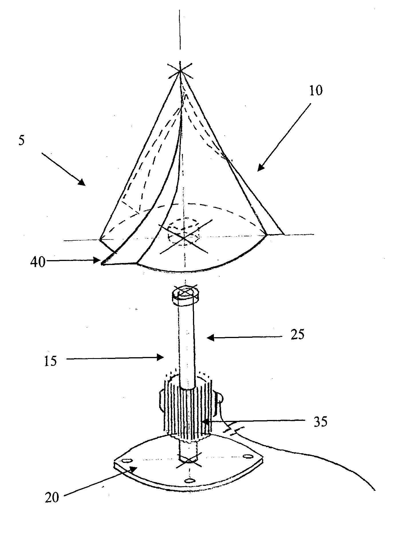
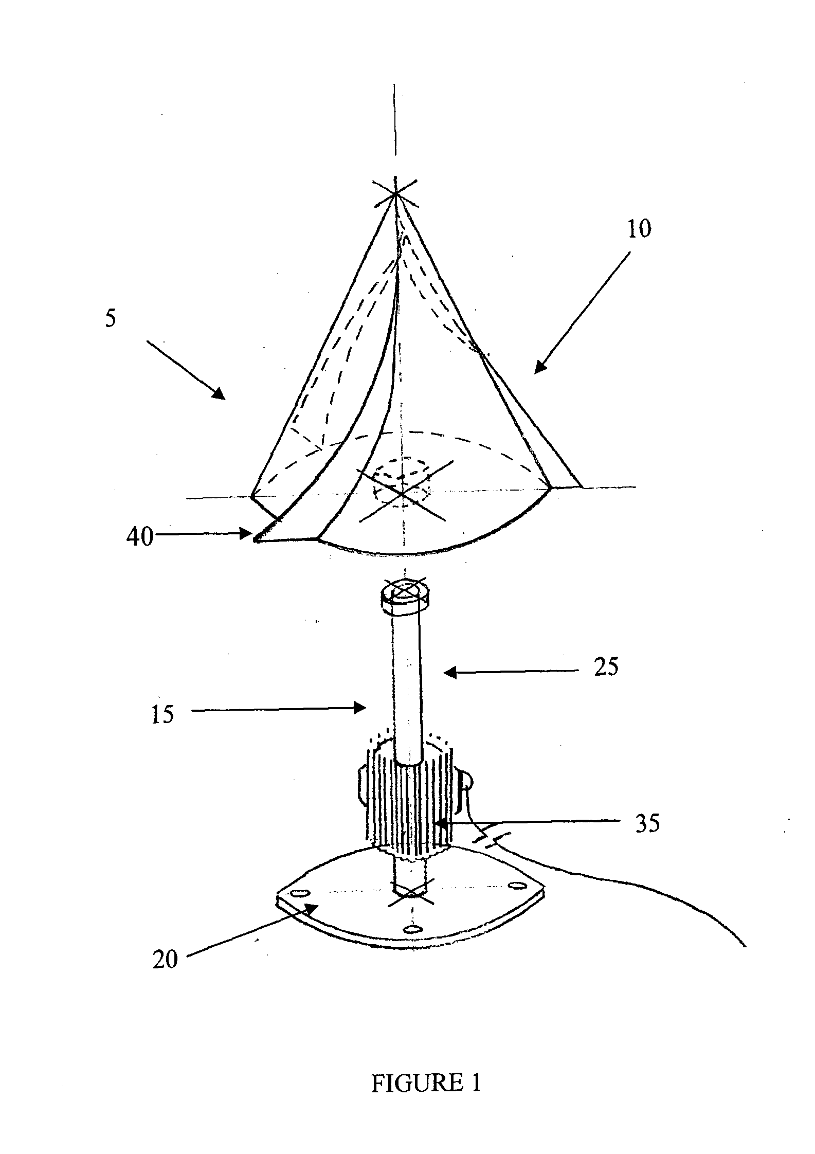
[0050]FIG. 1 illustrates an exploded view of an embodiment of a hybrid wind-solar device (5) of the invention. The outer wind-capture assembly (10) consists of a fabricated or formed outer structure. On the exterior surface of the outer wind-capture assembly (10), are affixed solar PV panels, membranes, or a similarly suitable conductive skin to collect solar energy. The solar energy is transferred via a harvesting wire network for use as required.

[0051]The turbine assembly (15) includes an anchoring base (20) for securing to an immovable surface; an output shaft (25) emanating from the anchoring base (20); and a turbine (35) positioned on the axis of the output shaft (25). In the embodiment shown in FIG. 1, the output shaft (25) is fitted with no less than two sets of precision bearings.

[0052]Assembly of the hybrid wind-solar device (5) is completed by mounting the outer wind-capture assembly (10) over the turbine assembly (15). Bearing sockets (not shown) in the outer wind-capture...


PUM


Abstract

Disclosed is a hybrid wind-solar energy device comprising: a) a wind-capture assembly comprising: i) one or more wind sails evenly distributed circumferentially around a central axis thereof; and ii) a solar-energy capture means on an outer surface of the wind-capture assembly; and c) a turbine assembly comprising an anchoring base, an electrical generator and an output shaft; the wind-capture assembly rotatably mounted on the output shaft and coupled thereto; the hybrid wind-solar energy device configured to convert energy harnessed by the wind capture assembly to electrical energy, wherein: interaction of the one or more wind sails with wind induces rotation of the wind-capture assembly and turbine assembly around the central axis; and the outer surface of the wind capture assembly is directly exposed to sunlight throughout daylight hours.

Description

[0001]FIG. 1 illustrates an exploded view of an embodiment of a hybrid wind-solar device (5) of the invention. The outer wind-capture assembly (10) consists of a fabricated or formed outer structure. On the exterior surface of the outer wind-capture assembly (10), are affixed solar PV panels, membranes, or a similarly suitable conductive skin to collect solar energy. The solar energy is transferred via a harvesting wire network for use as required.[0002]The turbine assembly (15) includes an anchoring base (20) for securing to an immovable surface; an output shaft (25) emanating from the anchoring base (20); and a turbine (35) positioned on the axis of the output shaft (25). In the embodiment shown in FIG. 1, the output shaft (25) is fitted with no less than two sets of precision bearings.[0003]Assembly of the hybrid wind-solar device (5) is completed by mounting the outer wind-capture assembly (10) over the turbine assembly (15). Bearing sockets (not shown) in the outer wind-capture...

Claims


Application Information

Patent Timeline
IPC IPC(8): F03D9/00H01L31/058H02J5/00
CPCF03D9/007H02K7/183F03D9/002Y02E10/74F03D3/061H02S10/10H02J5/00Y02E10/50H02J7/02H02S10/12F03D9/255F03D80/70F03D9/11F03D9/25
Inventor BRYSON, THOMAS PATRICK
Owner BRYSON THOMAS PATRICK
Learn More