
Camera stabilization mechanism

Inactive Publication Date: 2013-05-02
VANGUARD DEFENSE INT
View PDF5 Cites 27 Cited by
  • Summary
  • Abstract
  • Description
  • Claims
  • Application Information

AI Technical Summary

Benefits of technology

This patent describes a new camera mount that can be used to mount various camera systems on drones and aircraft. It is designed to be lightweight and isolate the camera system from vibrations and movements of the drone or aircraft. The mount includes flexible rod springs that dampen vibrations and absorb the main rotary component of the drone or aircraft. The camera mount can be easily attached to the frame of a small drone or aircraft and used to improve control and acquire targets with precision.

Problems solved by technology

One difficulty that arises with aerially-conveyed camera systems is the presence of vibration and other unwanted movements in the conveying aircraft.
Such vibrations may be transmitted to the camera, resulting in jitter and shaking, thus degrading the quality of the resulting imagery.
Indeed, in some circumstances, the degradation may be so great that certain camera systems may be unusable when conveyed by the aircraft.
In particular, camera systems capable of higher resolution imagery may be very susceptible to vibration, resulting in unusable images.

Method used


Image

  • Camera stabilization mechanism
  • Camera stabilization mechanism
  • Camera stabilization mechanism

Examples


Embodiment Construction

[0015]One or more specific embodiments of the present techniques will be described below. In an effort to provide a concise description of these embodiments, not all features of an actual implementation are described in the specification. It should be appreciated that in the development of any such actual implementation, as in any engineering or design project, numerous implementation-specific decisions must be made to achieve the developers' specific goals, such as compliance with system-related and business-related constraints, which may vary from one implementation to another. Moreover, it should be appreciated that such a development effort might be complex and time consuming, but would nevertheless be a routine undertaking of design, fabrication, and manufacture for those of ordinary skill having the benefit of this disclosure.

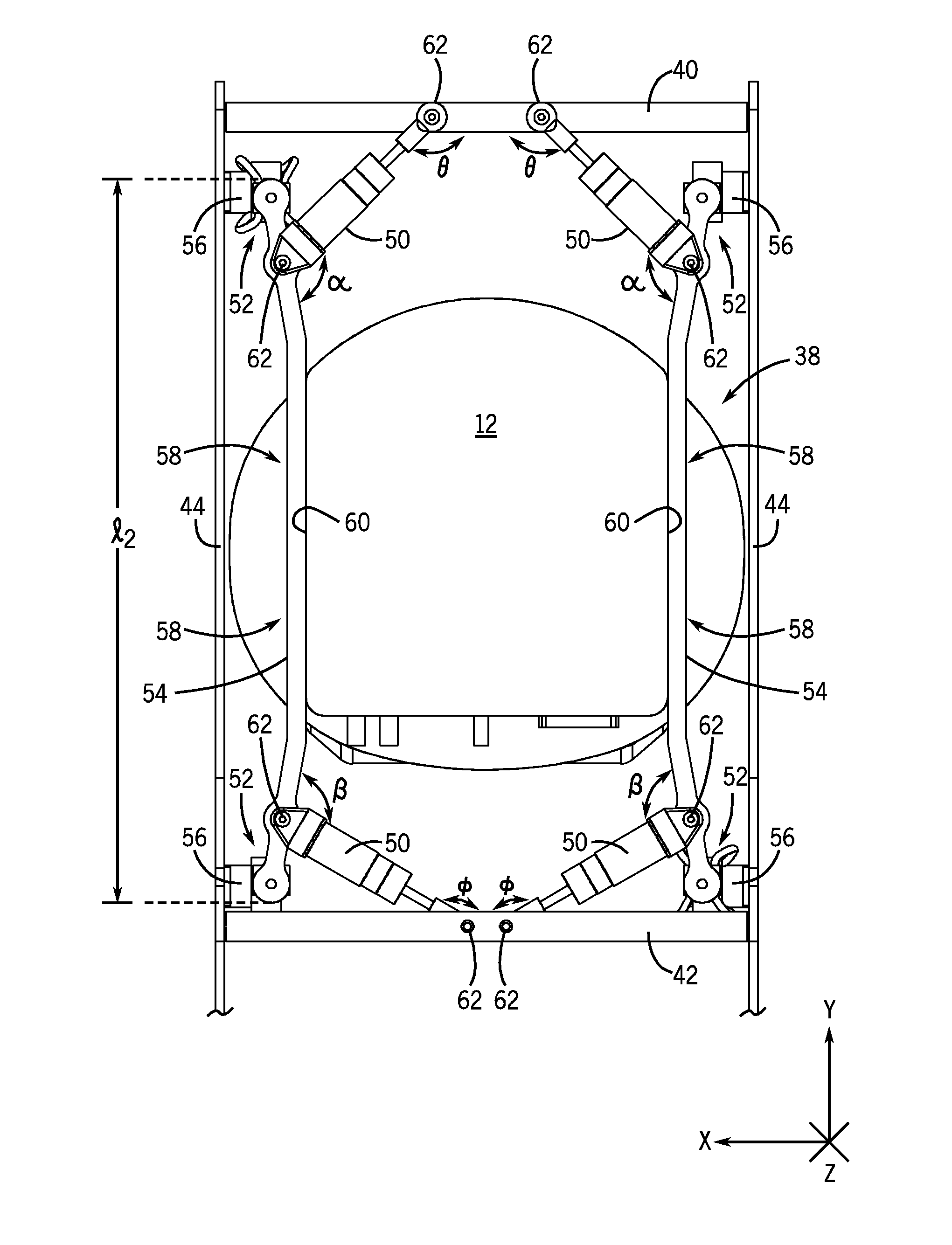
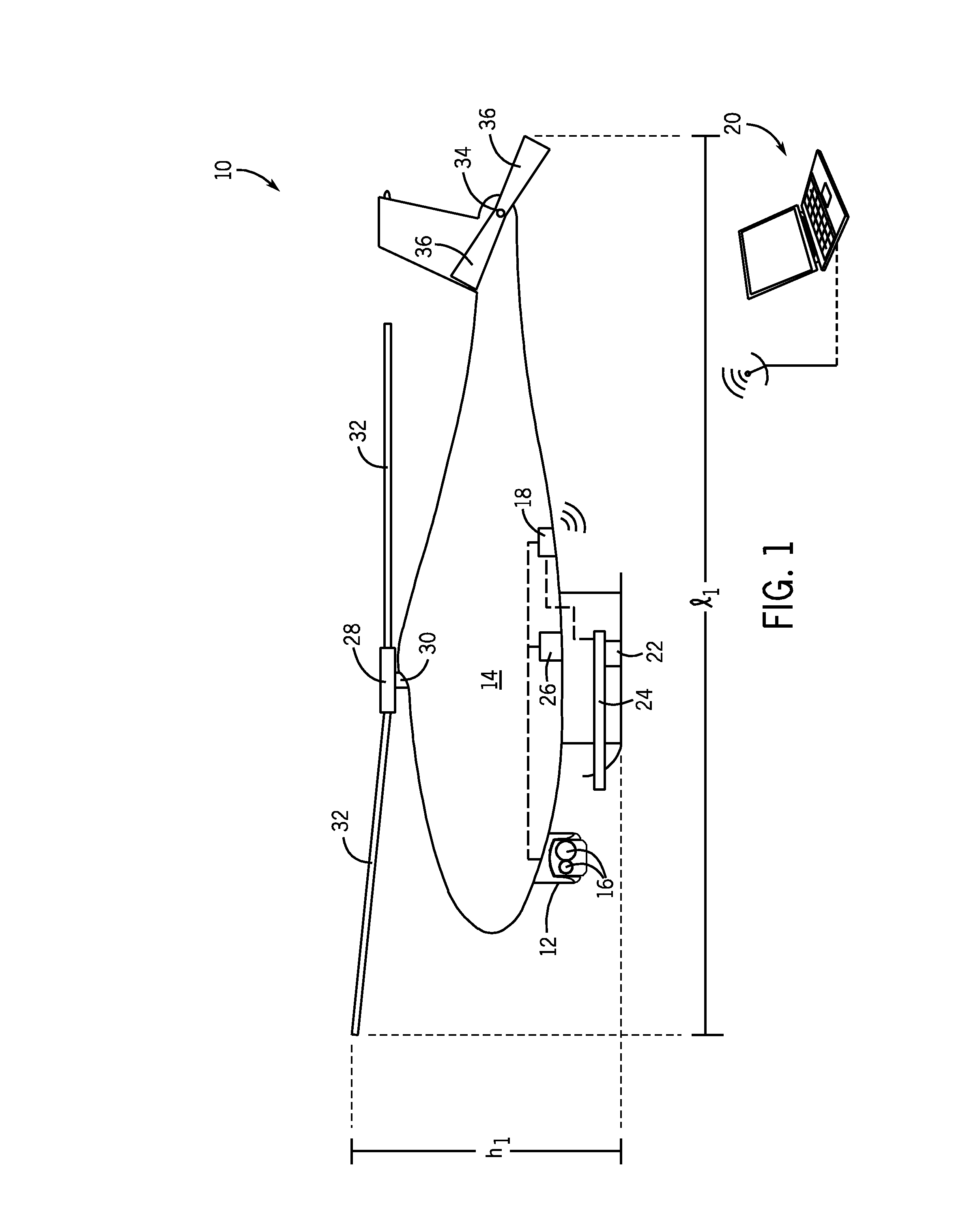
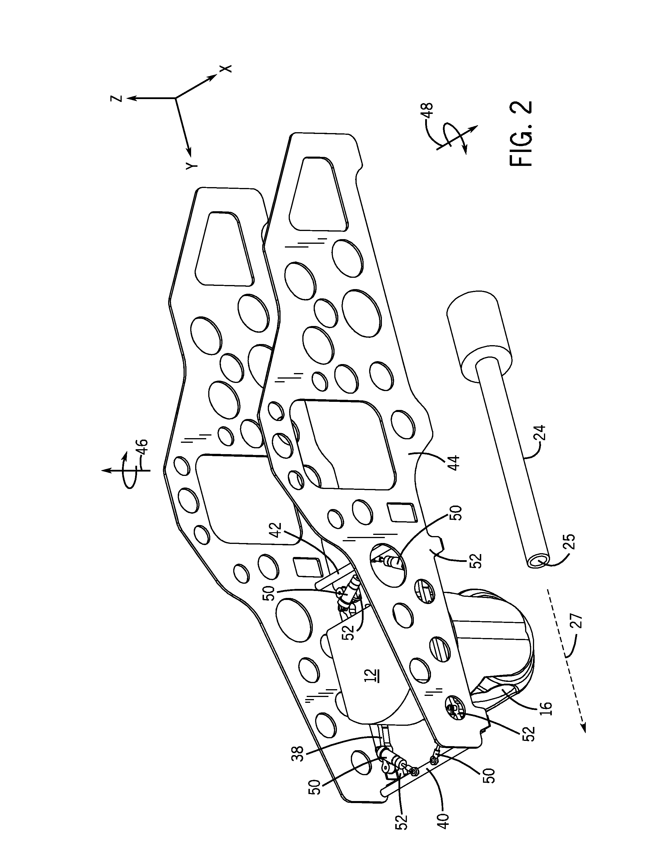
[0016]FIG. 1 is illustrative of a UAS 10. While the UAS 10 represented in the figure is a helicopter system, aspects of this disclosure could be applied ...


PUM


Abstract

Camera mount systems are disclosed herein. In one embodiment, a camera mount system is provided, including a first and a second axial arm configured to mount a camera system. The camera mount system further includes a plurality of pistons configured to attach the first and the second axial arms to a vehicle frame. The camera mount system also includes a plurality of springs configured to attach the first and the second axial arms to the vehicle frame, wherein the first and the second axial arms are disposed underslung to the vehicle frame, and wherein the pistons enable a first movement of the first and the second axial arms about a geometric plane and the springs enable a second movement of the first and the second axial arms along an axis normal to the geometric plane.

Description

BACKGROUND[0001]The present disclosure relates generally to stabilization systems and, more particularly, to camera stabilization systems.[0002]This section is intended to introduce the reader to various aspects of art that may be related to various aspects of the present disclosure, which are described and / or claimed below. This discussion is believed to be helpful in providing the reader with background information to facilitate a better understanding of the various aspects of the present disclosure. Accordingly, it should be understood that these statements are to be read in this light, and not as admissions of prior art.[0003]A variety of situations exist in which a moving camera system may be desired. For example, an aerially-conveyed camera system may be used to assist law enforcement, to spot forest fires, to report vehicular traffic, and more generally, to provide for aerial images and video. Certain camera systems may be conveyed by fixed wing (e.g., airplane) or rotary win...

Claims


Application Information

Patent Timeline
IPC IPC(8): B64C27/00G03B17/00G03B39/00
CPCB64D47/08G03B15/006B64C2201/127B64C2201/024B64U10/10B64U2101/30B64U20/87
Inventor BUSCHER, MICHAEL SEANKULESZA, HENRY E.
Owner VANGUARD DEFENSE INT
Learn More