
Power system stabilization

a power system and stabilization technology, applied in the direction of power oscillation reduction/prevention, ac network circuit arrangement, electrical equipment, etc., can solve the problems of power system stability becoming an important issue, increasing power loading, and loss of a generator

Active Publication Date: 2013-04-25
GENERAL ELECTRIC CO
View PDF5 Cites 19 Cited by
  • Summary
  • Abstract
  • Description
  • Claims
  • Application Information

AI Technical Summary

Benefits of technology

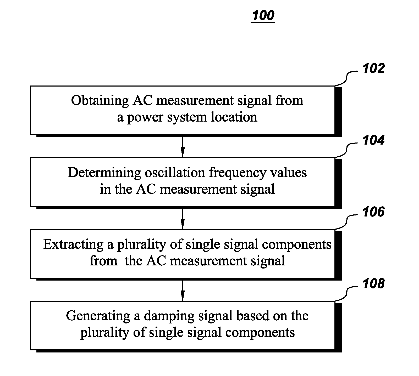
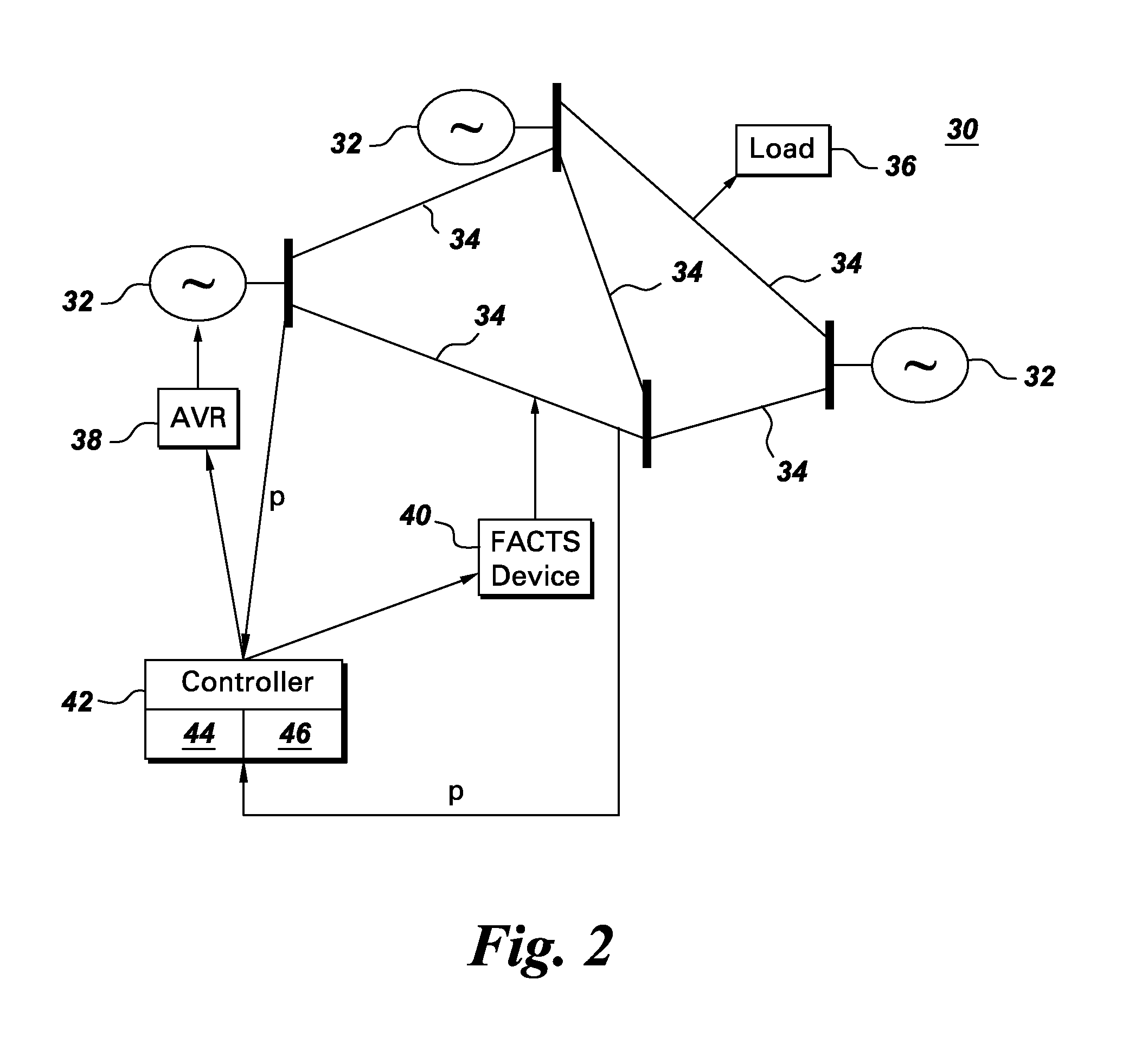
The present invention provides a method and system for damping power system oscillations. This is achieved by obtaining an AC measurement signal, determining the frequency of the oscillations, and extracting multiple single signal components from the measurement signal. These components are then combined to generate a damping signal that can be used to reduce the oscillations in the power system. The system includes a control device that generates the control signal for the damping device, which is used to adjust the power system in real-time to prevent instability and reduce damage caused by oscillations. The technical effects of the invention include improved stability, reduced damage, and improved control over power system oscillations.

Problems solved by technology

Since stressed conditions can lead a system to unstable conditions, power system stability has become an important issue.
The disturbance may be a fault, a loss of a generator or even a sudden increase in power loading.
Small signal stability is a power system stability issue related to low frequency oscillations between generator rotors.
When the power system is heavily loaded, it often exhibits multi-mode oscillations because machine rotors, behaving as rigid bodies, oscillate with respect to one another using the electrical transmission lines between them to exchange energy.
However, for separating the exact signals or for identifying the exact phase of the signal, not many solutions are available.
However, due to frequency domain approach which is limited by the decimation of unwanted frequencies with a per decade decay, it is almost impossible to extract frequencies which are very close to each other.
Frequency domain filters with very high orders may be able to provide some solution, but with the increase in the order of the filter, the delay associated with the filtering increases, which results in longer waiting time before the signals can be separated.

Method used


Image

  • Power system stabilization
  • Power system stabilization
  • Power system stabilization

Examples


Embodiment Construction

[0015]As used herein, the term “module” refers to software, hardware, or firmware, or any combination of these, or any system, process, or functionality that performs or facilitates the processes described herein.

[0016]When introducing elements of various embodiments of the present invention, the articles “a,”“an,”“the,” and “said” are intended to mean that there are one or more of the elements. The terms “comprising,”“including,” and “having” are intended to be inclusive and mean that there may be additional elements other than the listed elements.

[0017]In accordance with an embodiment of the present invention a system and method is proposed which extracts multiple signals of different frequencies from a measurement signal. The extracted multiple signals are used with appropriate gain and phase values by a damping controller to derive a control signal that can cancel each of the oscillating frequency components from the signal and can damp the oscillations.

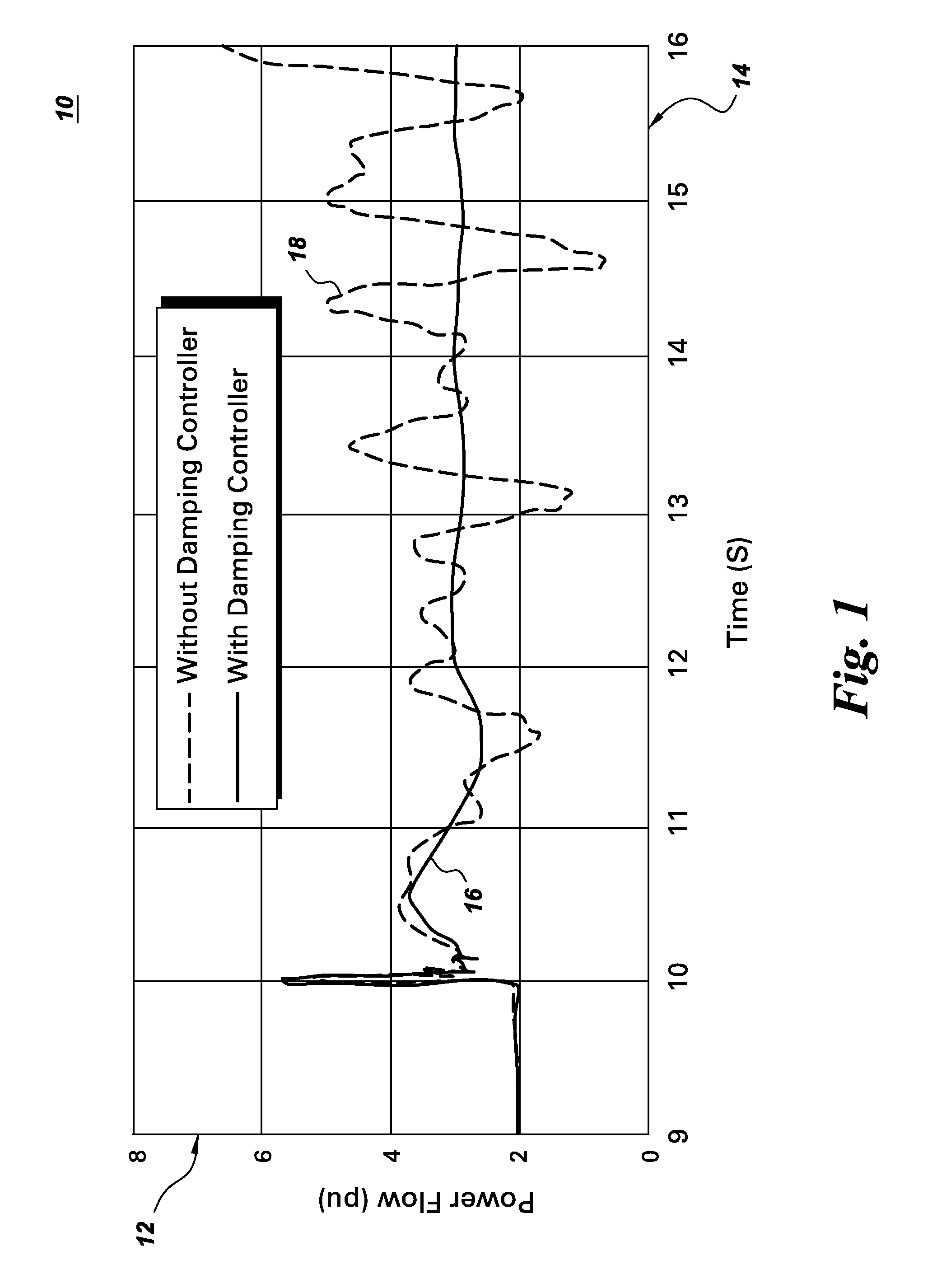
[0018]FIG. 1 shows a grap...


PUM


Abstract

A method of damping power system oscillations includes obtaining an AC measurement signal from a power system location and determining oscillation frequency values in the AC measurement signal. A plurality of single signal components are extracted from the AC measurement signal by subtracting a plurality of processed measurement signals from the AC measurement signal and a damping signal is generated based on the plurality of single signal components. Each of the plurality of processed measurement signals are generated by time delaying the AC measurement signal with a time delay associated with each of the oscillation frequency values other than the oscillation frequency value of the single signal component to be extracted.

Description

BACKGROUND[0001]Embodiments of the present invention relate generally to a power flow in a power system. More specifically, the embodiments relate to damping of power system oscillations.[0002]The power system is a complex network comprising of numerous generators, transmission lines, a variety of loads and transformers. With increasing power demand in the power system, some transmission lines are more stressed than was planned when they were built. Since stressed conditions can lead a system to unstable conditions, power system stability has become an important issue. In simple terms, power system stability is defined as the ability of the power system to return to a normal state after a disturbance. The disturbance may be a fault, a loss of a generator or even a sudden increase in power loading.[0003]Small signal stability is a power system stability issue related to low frequency oscillations between generator rotors. It has been the main reason for many power blackouts across th...

Claims


Application Information

Patent Timeline
IPC IPC(8): H02J3/24
CPCH02J3/24H02J3/241
Inventor RAY, SWAKSHARKOLWALKAR, AMOL RAJARAM
Owner GENERAL ELECTRIC CO
Learn More