
Bone fixation system with opposed mounting portions

Active Publication Date: 2013-04-11
ACUTE INNOVATIONS
View PDF19 Cites 57 Cited by
  • Summary
  • Abstract
  • Description
  • Claims
  • Application Information

AI Technical Summary

Benefits of technology

The patent text describes how trauma to the chest can result in multiple rib fractures, which can cause pain, respiratory distress, and potentially require sedation or intubation. The text describes a rib plating system that uses a U-shaped clip to prevent bone screws from backing out of the rib. However, the text suggests that the system could be improved to make clip installation easier and more customizable, to provide a better fit of the clips on bones of different size and shape, to make fastener installation easier and / or more reliable, or the like.

Problems solved by technology

Trauma to the torso can result in fracture of one or more ribs.
However, in cases of more severe trauma to the chest, a single rib may be fractured more severely and / or multiple rib fractures may occur.
This condition may result in severe respiratory distress, possibly requiring the patient to be sedated and / or intubated during early stages of healing.
Although bone screws can be used to secure bone plates to bone, rib bones have a thin cortex and are filled with spongy cancellous bone, neither of which can hold bone screws effectively, so the bone screws tend to pull out.
Fitting the clips of Ellis closely onto a rib can be a challenge.
Even along the same rib, a clip sized to fit at one position of the rib may be too small or oversized at other positions.
This approach has a number of disadvantages: measuring the rib for each clip can be time-consuming and may be prone to errors; a relatively large set of clips, and especially bone plates with a pair of integral clips, may be necessary to accommodate all rib sizes accurately; and ribs vary in cross-sectional shape, which can make the fit imperfect even with the most careful measurement.

Method used


Image

  • Bone fixation system with opposed mounting portions
  • Bone fixation system with opposed mounting portions
  • Bone fixation system with opposed mounting portions

Examples


example 1

Exemplary Clip Collapse with an Installation Tool

[0132]This example describes further aspects of tool 250 and clip 60 (see Sections I and II), particularly an exemplary configuration produced by collapsing the clip with jaws 272, 274 of the tool; see FIGS. 27-29.

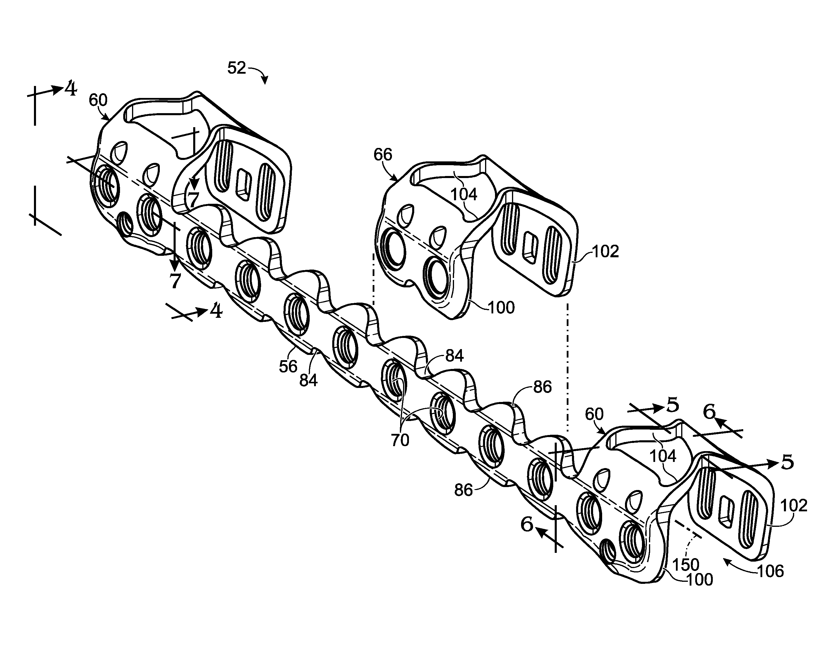
[0133]FIGS. 27 and 28 shows tool 250 attached to and operatively engaged with clip 60 respectively before and after the clip has been collapsed against bone 54 by the clamping device of the tool. FIG. 27 shows proximal and distal mounting portions 100, 102 defining respective planes 452, 134 that are parallel to each other. In other embodiments, planes 452, 134 may be inclined from parallel to each other by any suitable angle. In the depicted configuration, proximal mounting portion 100 is placed against bone before the clip is collapsed. However, in other configurations, the mounting portions may be spaced more equally from the bone before collapse, or the distal mounting portion may be closer to the bone. FIG. 28 shows dis...

example 2

Selected System Embodiments

Clip with Collapsible Portion

[0136]This example describes selected system embodiments of the present disclosure related to a clip having a collapsible portion, presented as a series of indexed paragraphs.

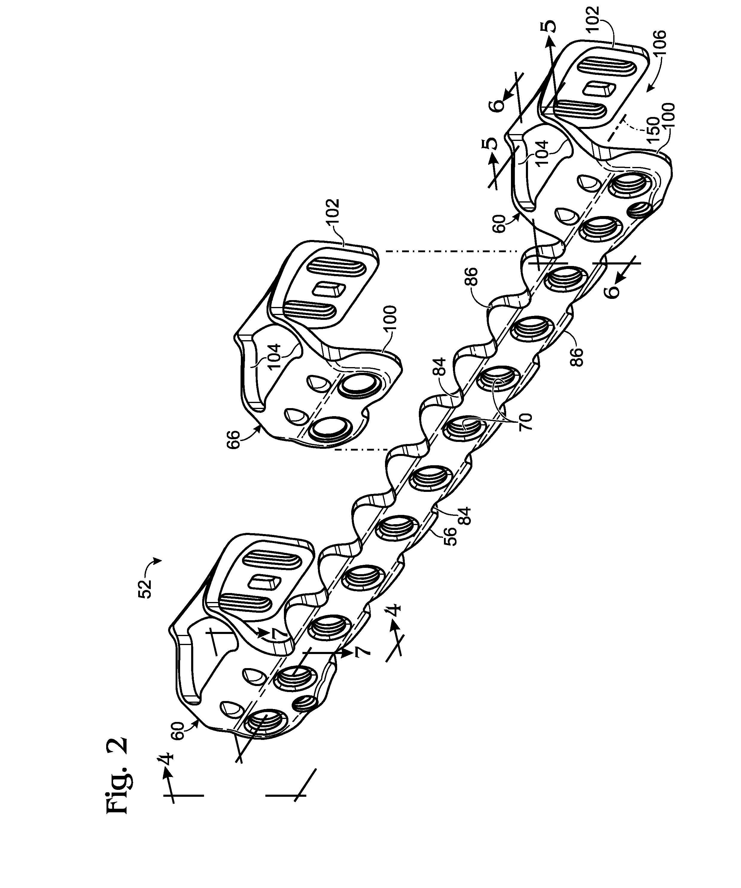
[0137]1. A system for bone fixation, comprising: (A) a clip including first and second mounting portion and a selectively collapsible portion connecting the mounting portions, the mounting portions respectively defining a first aperture and a second aperture that are aligned with each other, the mounting portions and the collapsible portion collectively defining a cavity configured to receive a bone such that the mounting portions opposingly flank the bone and an axis defined collectively by the first and second apertures extends through the received bone from the first aperture to the second aperture.

[0138]2. The system of paragraph 1, wherein the collapsible portion is configured to fold at one or more predefined sites as the clip members are urged towar...

example 3

Selected Methods

[0154]This example describes selected methods of the present disclosure, presented as a series of indexed paragraphs.

[0155]1. A method of fixing bone, the method comprising: (A) connecting a first mounting portion and a second mounting portion of a fixation device to an installation tool; (B) disposing the first mounting portion and the second mounting portion across a bone from each other; (C) urging the first and second mounting portions toward each other with jaws of the tool such that the tool is clamped to the bone; and (D) securing the first and second mounting portions to the bone with a fastener extending from a first aperture defined by the first mounting portion, through the bone, and into a second aperture defined by the second mounting portion.

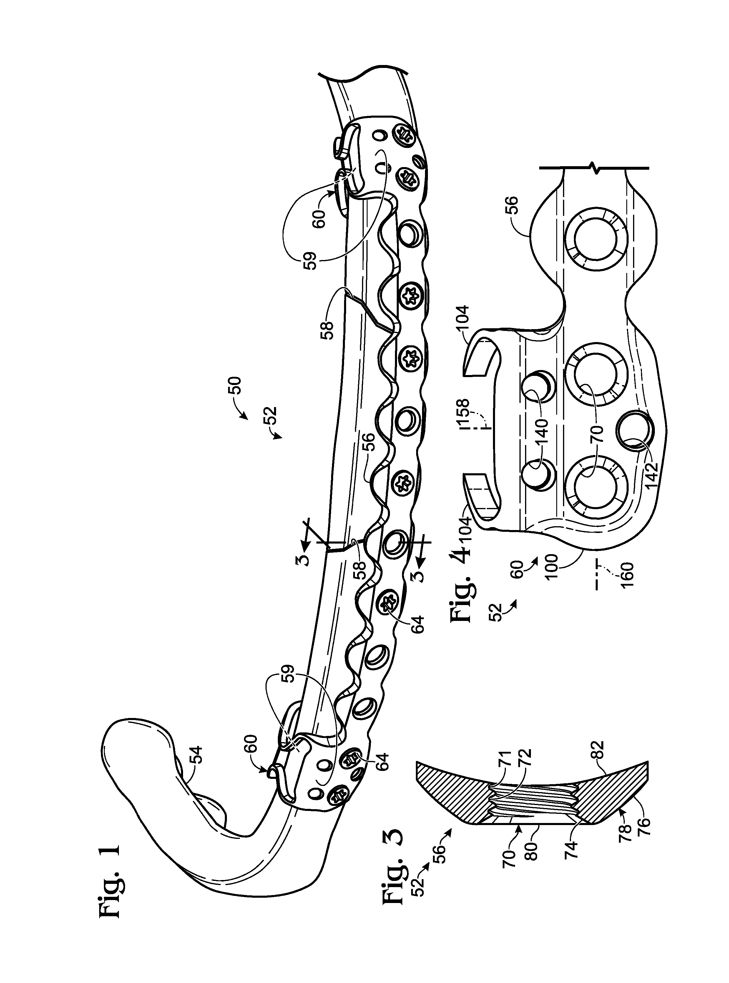
[0156]2. The method of paragraph 1, wherein the fixation device includes a spanning portion, and wherein the spanning portion extends along the bone from the first mounting portion after the mounting portions are se...


PUM


Abstract

System, including methods, apparatus, and kits, for bone fixation using a fixation device including a mounting portion and a fastener that attaches to the mounting portion. In some embodiments, the fixation device may include first and second mounting portions configured to be disposed across a bone from each other and secured with a fastener that extends from one of the mounting portions, through the bone, and to the other mounting portion. The system also may include a tool to facilitate installation of the fixation device.

Description

CROSS-REFERENCE TO PRIORITY APPLICATION[0001]This application is based upon and claims the benefit under 35 U.S.C. §119(e) of U.S. Provisional Patent Application Ser. No. 61 / 542,046, filed Sep. 30, 2011, which is incorporated herein by reference in its entirety for all purposes.INTRODUCTION[0002]The rib cage, or thoracic cage, is composed of bone and cartilage that surround the chest cavity and organs therein, such as the heart and the lungs. In humans, the rib cage typically consists of 24 ribs, twelve thoracic vertebrae, the sternum (or breastbone), and the costal cartilages. The ribs articulate with the thoracic vertebrae posteriorly and, with the exception of the bottom two pairs of ribs (the floating ribs), are connected to the sternum anteriorly using the costal cartilages.[0003]Trauma to the torso can result in fracture of one or more ribs. Frequently, a simple rib fracture is nondisplaced, so that reduction and / or internal fixation of the fracture may not be required. Howeve...

Claims


Application Information

Patent Timeline
IPC IPC(8): A61B17/80
CPCA61B17/80A61B17/863A61B2019/461A61B17/8869A61B17/82A61B2017/1792A61B17/808A61B17/8076A61B17/8863A61B17/1728A61B17/8057A61B2090/034A61B90/92A61B2090/061A61B17/1792A61B17/8061A61B17/8085A61B17/0643A61B2017/0645A61B17/064
Inventor BERNSTEIN, OREN S.GILLARD, JOELTHORSELL, ERICHAISLIP, SARALOUCKS, KYLE A.SEYKORA, ANDREW W.
Owner ACUTE INNOVATIONS
Learn More