Water recovery and acid gas capture from flue gas

Inactive Publication Date: 2013-04-11
PHILLIPS 66 CO
View PDF8 Cites 11 Cited by
  • Summary
  • Abstract
  • Description
  • Claims
  • Application Information

AI Technical Summary

Benefits of technology

The patent text describes methods for recurring water and acid gas recovery from flue gas produced by combustion in a boiler. The flue gas is cooled in a water spray tower to condense water vapor and produce recirculating water. A chemical is added to the water. A slipstream is then taken off the recirculating water as make-up water. Additionally, the patent describes a method of collecting production fluids from a steam-assisted gravity drainage operation and converting them for use in the operation. The technical effects include efficient gas and water recovery, reduced sulfur content in fuel gas, and the use of recirculating water in the steam-assisted gravity drainage operation.

Problems solved by technology

There is a strong possibility that government regulations on water use may eventually require that saline water be utilized for such operations, rather than fresh or “non-saline” water.
However, saline water typically contains a high amount of total dissolved solids, and it is expensive to treat such water streams to obtain water suitable for use in steam-assisted hydrocarbon production.
Discarding these condensable components can constitute a substantial loss in available heat energy.
However, U.S. Pat. No. 7,066,396 provides no teaching or suggestion for producing make-up water for a steam-assisted gravity drainage system while simultaneously removing at least one acid gas from the flue gas.
However, U.S. Pat. No. 4,799,941 provides no teaching or suggestion regarding the production of make-up water for a steam-assisted gravity drainage system while simultaneously recovering at least one acid gas present in the flue gas.

Method used


Image

  • Water recovery and acid gas capture from flue gas
  • Water recovery and acid gas capture from flue gas
  • Water recovery and acid gas capture from flue gas

Examples


example 1

[0044]The presence of carbonate or bicarbonate above a certain threshold concentration in the first aqueous stream can precipitate, potentially fouling (or even plugging) the water flow inside the spray tower. This fouling or plugging can be controlled by any of several methods, including regulating the pH of the spray water (via caustic addition) to control the amount of carbon dioxide absorbed

[0045]It is possible to control the amount of carbon dioxide absorbed into the water spray by regulating the pH. The results of two experiments conducted in our laboratory demonstrate this. In the first experiment, methane gas containing 100 ppm H2S was combusted and passed through a glass column with glass bead packing and water was introduced to cool the flue gas. The water stream from the column (containing the water spray plus the water condensed from the flue gas) was collected in a vessel where it was neutralized with a caustic solution made by adding 1 gram of a 20% (by wt.) NaOH solut...

example 2

[0047]An additional experiment was conducted to further optimize the pH range at which carbon dioxide absorption is maximized. For this experiment, 10 ppm of ethyl mercaptan was added to a methane fuel, and the mixture combusted to make a flue gas. To maintain the spray water at a pH of 6 required the addition of 400% more caustic than was required to maintain a pH of 5. Thus, it was concluded that a pH of around 6 was the threshold for significant absorption of carbon dioxide from flue gas into the spray water.


PUM

PropertyMeasurementUnit
Fractionaaaaaaaaaa
Fractionaaaaaaaaaa
Acidityaaaaaaaaaa

Abstract

Methods for removing acid gases and recovering water from flue gas. A flue gas is introduced into a water spray tower and is cooled by direct contact with a sprayed aqueous stream to condense a portion of the water vapor in the flue gas. Acid gases present in the flue gas are absorbed into the aqueous mixture, and a chemical added to the stream facilitates conversion of absorbed acid gases. The aqueous stream leaving the spray tower is next treated to remove contaminants, such as carbonates and bicarbonates, thereby producing a cleaned aqueous stream that may be split into a stream that is cooled prior to reuse in the spray tower, as well as a stream that is fed back to the boiler.

Description

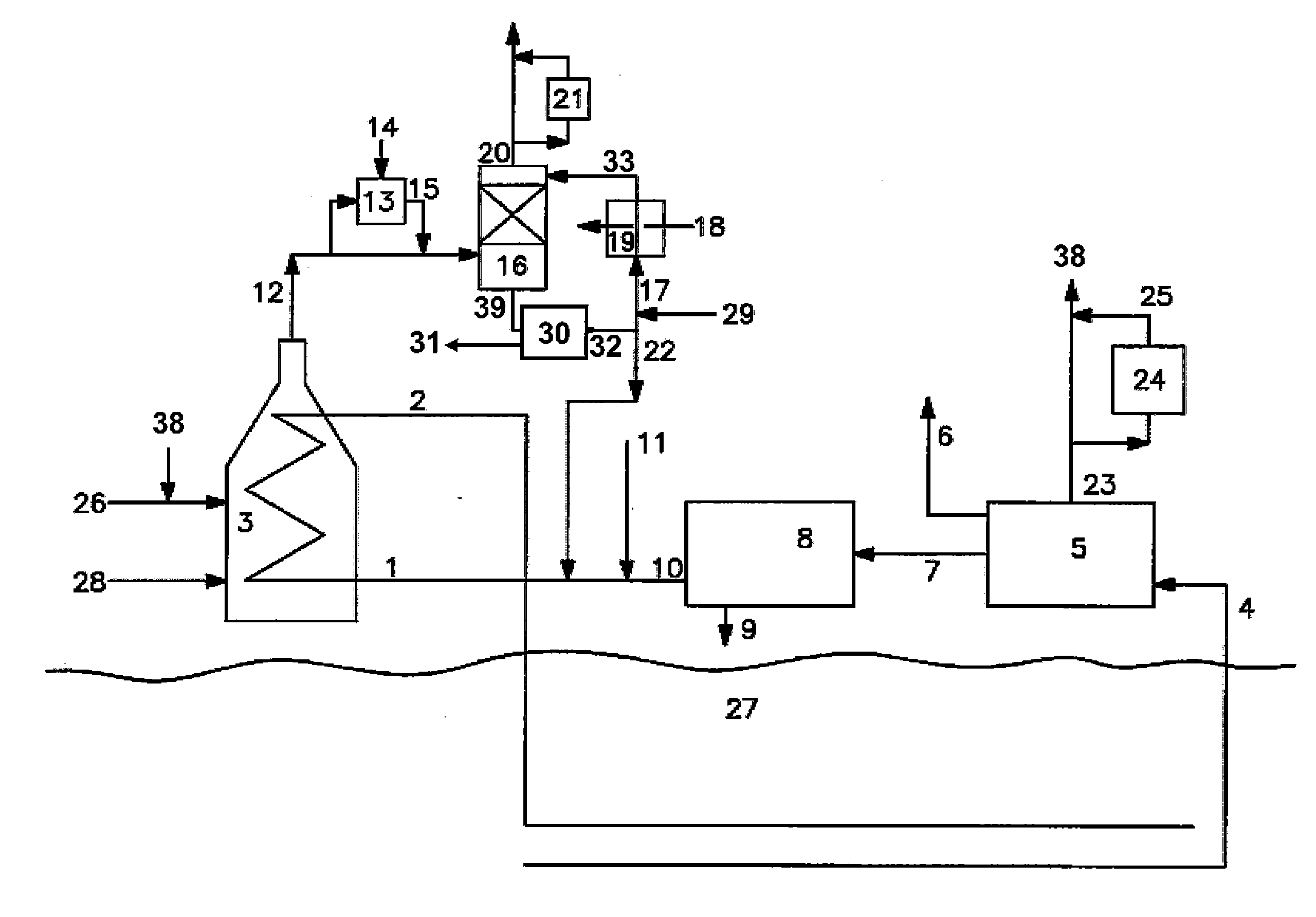
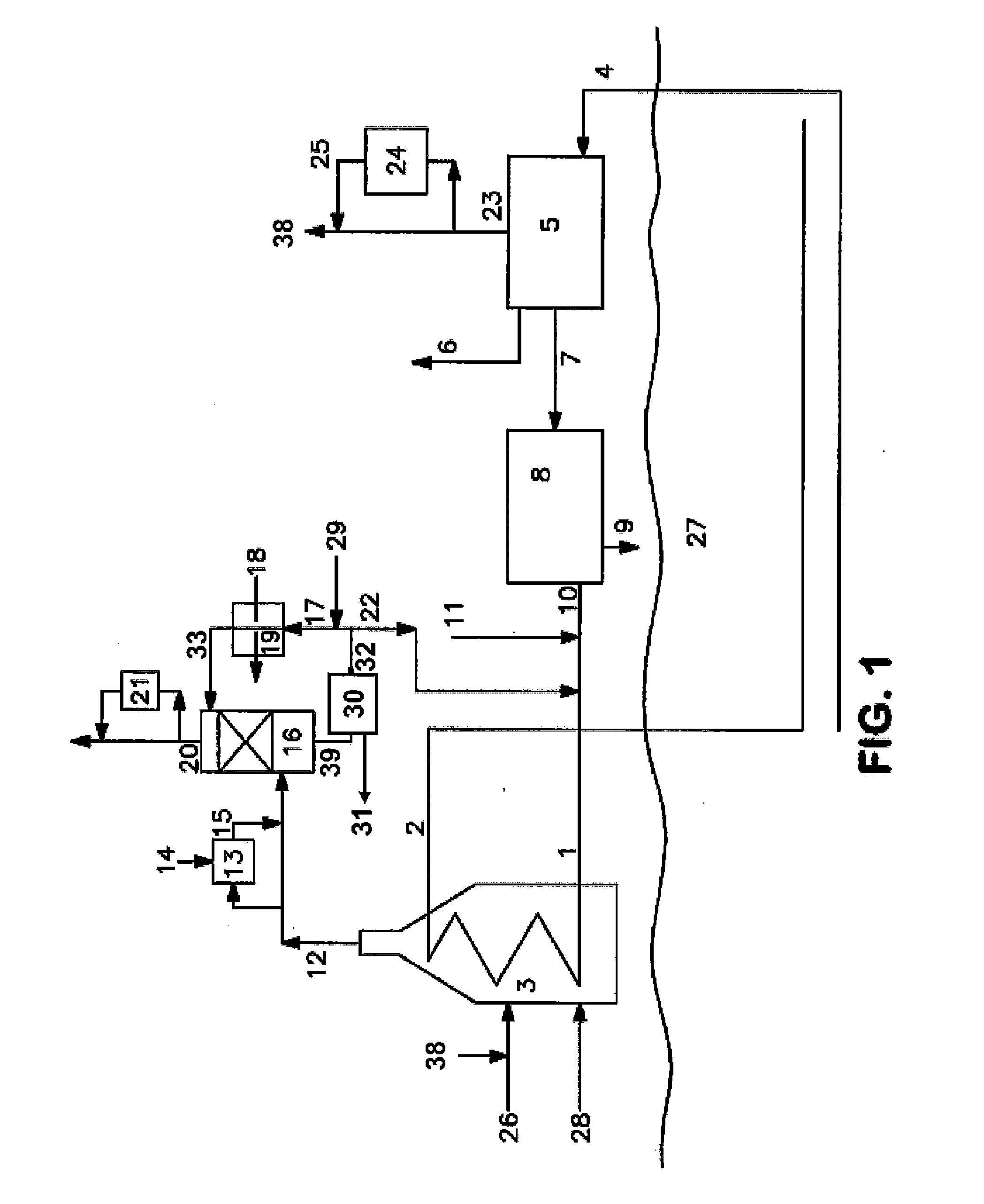
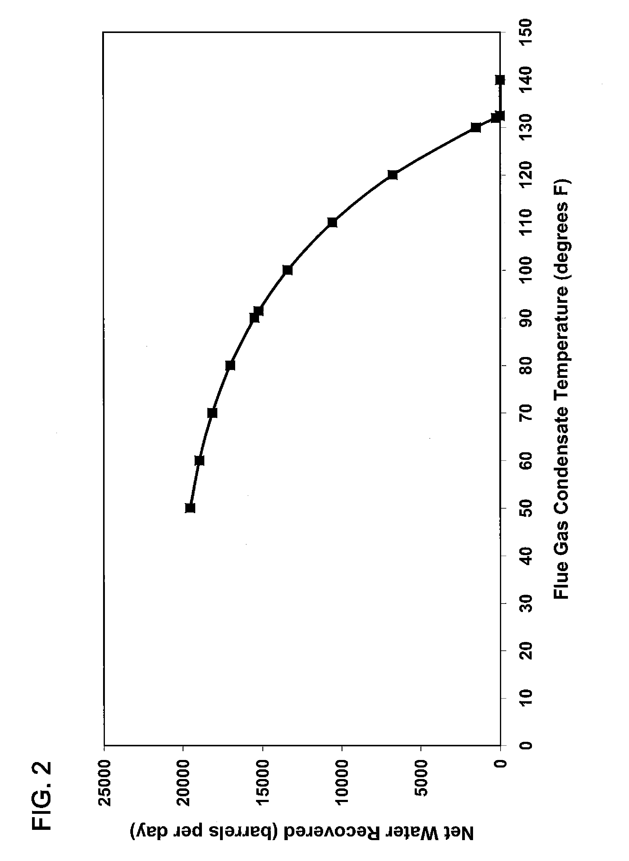
CROSS-REFERENCE TO RELATED APPLICATIONS[0001]This application is a non-provisional application which claims benefit under 35 USC §119(e) to U.S. Provisional Application Ser. No. 61 / 545,837 filed Oct. 11, 2011, entitled “WATER RECOVERY AND ACID GAS CAPTURE FROM FLUE GAS,” which is incorporated herein in its entirety.STATEMENT REGARDING FEDERALLY-SPONSORED RESEARCH OR DEVELOPMENT[0002]NoneFIELD OF THE INVENTION[0003]Methods and systems for removing acid gases from a flue gas while simultaneously generating make-up water by recovering water from steam-assisted production boiler flue gas.BACKGROUND[0004]Obtaining adequate water for future steam-assisted hydrocarbon production is an area of critical concern. There is a strong possibility that government regulations on water use may eventually require that saline water be utilized for such operations, rather than fresh or “non-saline” water. However, saline water typically contains a high amount of total dissolved solids, and it is expens...

Claims


Application Information

Patent Timeline
IPC IPC(8): B01D53/40B01D53/48B01D53/56
CPCB01D53/40B01D53/56B01D53/485B01D53/77F23J15/04Y02E20/363B01D2258/0283F23J2219/40F23J2219/70F22B37/008F23J15/06Y02P80/15
Inventor LATIMER, EDWARD G.SCHUETTE, GEORGE F.AICHELE, CLINT P.LOESCHER, MITCHELL E.HEALD, RANDALL L.
Owner PHILLIPS 66 CO
Why Eureka
Try Eureka