
Forced Insertion Concentric Ground-Coupled Heat Exchanger for Ground Source Heat Pumps

a heat exchanger and concentric ground technology, applied in geothermal energy generation, heat production devices, light and heating equipment, etc., can solve the problems of poor heat transfer capability when compared to metals, and achieve the effect of short installation time requirements

Inactive Publication Date: 2013-04-11
WINN JR BERNARD MEREDITH
View PDF6 Cites 14 Cited by
  • Summary
  • Abstract
  • Description
  • Claims
  • Application Information

AI Technical Summary

Benefits of technology

The patent describes a method of installing pipes to transport heat between buildings and heat exchangers. The trenches used for installation are small, with the average depth being about 18 inches. The land surface is only minimally impacted by the installation. The technical effect of this method is that it minimizes disruption to the land surface while still allowing for effective heat transfer.

Problems solved by technology

Currently, GSHP in-ground Heat exchangers are made of high density polyethylene (HDPE) which is known to have poor heat transfer capability when compared to metals.

Method used


Image

  • Forced Insertion Concentric Ground-Coupled Heat Exchanger for Ground Source Heat Pumps
  • Forced Insertion Concentric Ground-Coupled Heat Exchanger for Ground Source Heat Pumps
  • Forced Insertion Concentric Ground-Coupled Heat Exchanger for Ground Source Heat Pumps

Examples


Embodiment Construction

[0026]Heat Exchanger Design:

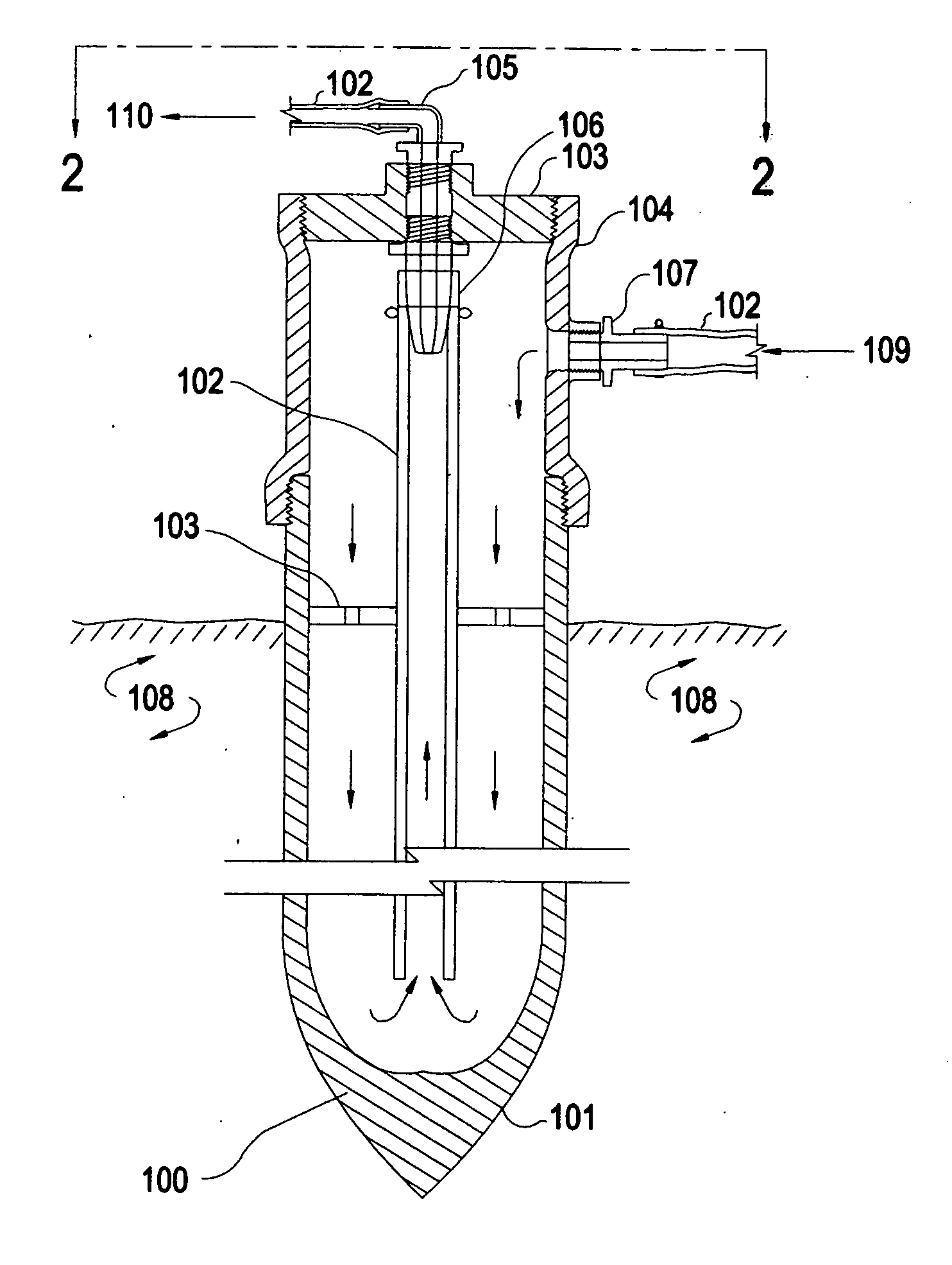
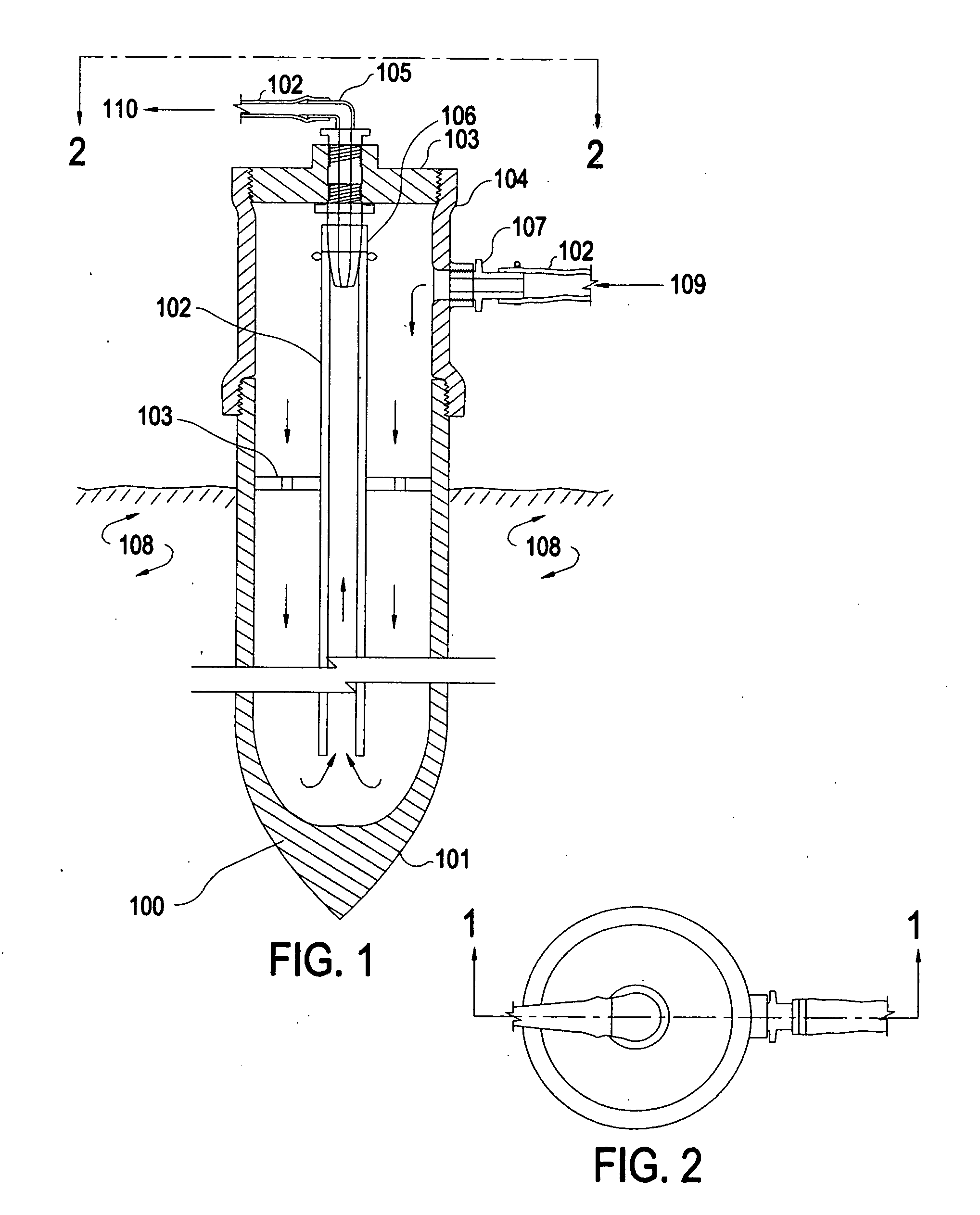
[0027]The concentric tube ground source heat exchangers have been known as prior art for many years [Oliver, J., and H. Braud, 1981. Thermal exchange to earth with concentric well pipes. Transactions of ASAE. 24(4): 906-910]. Notes the use of concentric pipe Heat exchangers]. Also, in patent application Ser. No. 12 / 720052 by Lawless et al, the use of concentric Heat exchangers is noted. The specific designs for existing concentric Heat exchangers utilize complicated ribbed tubes and special head plumbing. Today's invention provides a much-simplified design, consisting of standard piping, tubing, and fittings (100). The invention provides a novel and inexpensive method of installing the inner concentric flow tube (106) into the pointed 20 to 40 foot long heat exchange pipe (101) by using standard materials arranged in a novel fashion to accomplish the objective. The novel means to provide the concentric annular flow is shown in FIG. 1 and encompasses the u...


PUM


Abstract

This invention consists of a novel heat exchanger design and a novel means of its installation for Ground-Source Heat Pump Systems' ground heat gain / rejection loops. This improvement reduces the installation cost of such systems by method of placement and exchanger design. The Heat exchanger is a metal pipe, 20 to 40 feet long, approximately 1.25 to 2 inch diameter, containing an internal polymeric tube, installed in the pipe concentrically to carry the heat exchange medium from or to the bottom of the pipe; the pipe being inserted into the ground by means of a ballistic launcher or direct-push machine or by manual means. This system reduces the installation costs. The current art calls for extensive trenching or drilling, and yields high costs and detrimental impacts on property. This invention reduces surface impact areas. The only trenching connects the building to the tops of the Heat exchangers.

Description

BACKGROUND OF THE INVENTION[0001]The field of the invention is the ground source heat pump system, and more specifically, the portion of that field that exchanges heat with the earth. Ground source heat pumps (GSHP) are well established as being efficient means to heat and cool buildings. Rather than use the ambient air as a source or sink for the heat required for building heat addition (in winter) and cooling (in summer), the GSHP relies on the fact that the underground is relatively constant in temperature year round. The main disadvantage has been the initial cost of the GSHP system, caused by the cumbersome, costly and detrimental means to install the in-ground Heat exchanger. Other parts of a GSHP system are similar in design to the conventional ambient air source heat pump and are not part of the present invention.[0002]There are two general types of systems practiced for using the earth's heat as a source and a sink for heating and cooling buildings, open loop and closed loo...

Claims


Application Information

Patent Timeline
IPC IPC(8): F24J3/08
CPCF24J3/084Y02E10/125F24T10/17F24T2010/53Y02E10/10
Inventor WINN, JR., BERNARD MEREDITH
Owner WINN JR BERNARD MEREDITH
Learn More