
Three phase reactor

a three-phase reactor and slurry bubble technology, applied in indirect heat exchangers, chemical/physical/physicochemical processes, lighting and heating apparatus, etc., can solve the problems of high cost and difficulty in scaling up of slurry bubble column reactors, the relationship between the reactor vessel diameter and the reactor vessel height, and the rate of deactivation of fischer-tropsch catalysts. , to achieve the effect of high production level and high carbon monoxide conversion ratio

Active Publication Date: 2013-04-04
EMERGING FUELS TECH
View PDF8 Cites 2 Cited by
  • Summary
  • Abstract
  • Description
  • Claims
  • Application Information

AI Technical Summary

Benefits of technology

[0019]In this invention, it is therefore possible to economically operate at linear velocities that are low enough to be in the homogenous gas flow regime, resulting in a high percentage of carbon monoxide conversion in a relatively short reactor height, while concurrently using a large synthesis gas feed flow that is distributed along the length of the reactor vessel. Thus, the present invention allows for a high carbon monoxide conversion per reactor unit volume resulting in a high level of production per reactor.
[0020]Compared to prior art slurry bed reactors, the vessel diameter according to the present invention does not have to be within the same range as the reactor diameter in typical slurry bed Fischer-Tropsch reactor technology. The total synthesis gas feed flow, which will determine the reactor capacity, will be accommodated for by increasing the reactor vessel length.
[0021]For example, a typical slurry bed with a diameter of 10 m has a cross sectional area (not including internal structures) of about 78.54 m2. The reactor of the present invention will have a similar cross sectional area (at its higher point) if the vessel diameter is 5.25 m and the vessel length is 30 m. The number of manufacturers worldwide that can produce a 5.25 m diameter vessel is more abundant than the number of manufacturers that can produce a vessel with a 10 m diameter. Thus, the present invention reduces duration of manufacturing and increases the number of potential fabricators.
[0022]In the present invention, the catalyst located in the slurry mixture will be subjected to a much milder attrition regime due to the low gas linear velocity and the low reactor height.
[0023]Compared to prior technology, the reactor of the present invention is much quicker and less costly to scale up. The hydrodynamic regime can be studied by using sectional slices of the reactor, preferably at different vessel diameters. The reactor regime will be more predictable because an increase in vessel length will have only a small effect on the reactor hydrodynamics, and as such, this effect will only decrease as the ratio between the vessel length and the vessel diameter increases. The implementation of low gas linear velocity will also allow for the hydrodynamic regime to be more easily modeled and understood.

Problems solved by technology

However, the slurry bubble column reactor is both costly and difficult to scale up.
One of the main constraints with current technology for three phase reactors, and in particular Fischer-Tropsch slurry bed reactors, is the relationship between the reactor vessel diameter and the reactor vessel height.
High water partial pressures increase the rate of deactivation of Fischer-Tropsch catalysts and are therefore undesirable.
The reactor would thus have a much lower total productivity than desired.
Due to this increase in gas hold up, there is an upper limit for the gas linear velocity, above which, the reactor productivity actually declines.
Because of the operating conditions, and the large reactor shell dimensions, there are very few places in the world where these vessels can be constructed.
This has a severe negative effect toward the application of the Fischer-Tropsch slurry bed technology worldwide.
Another problem with current slurry bed reactor technology is the complex hydrodynamic regime inside the slurry bed units.
Under these conditions it is difficult, costly and complex to predict the reactor hydrodynamic profile inside the large commercial unit.
Yet, another problem with current slurry bed reactor technology is the difficulty with separating the catalyst from the liquid hydrocarbon products.
If the catalysts attrite, small particles are created which lowers the efficiency of the solid-liquid separation system, irrespective of whether the assembly consists of filters, settlers, hydro cyclones, magnetic techniques, or a combination of the above techniques.
The central section of the reactor has a higher than average gas hold up and bubble size and therefore high turbulence.
Therefore the particle to particle collisions and collisions with reactor internals such as cooling coils caused by catalysts moving at high linear velocities in the central section of the reactor will inevitably result in catalyst attrition.

Method used


Image

  • Three phase reactor
  • Three phase reactor
  • Three phase reactor

Examples


Embodiment Construction

[0027]The embodiments discussed herein are merely illustrative of specific manners in which to make and use the invention and are not to be interpreted as limiting the scope of the instant invention.

[0028]While the invention has been described with a certain degree of particularity, it is to be noted that many modifications may be made in the details of the inventions construction and the arrangement of its components without departing from the spirit and scope of this disclosure. It is understood that the invention is not limited to the embodiment set forth herein for purposes of exemplification.

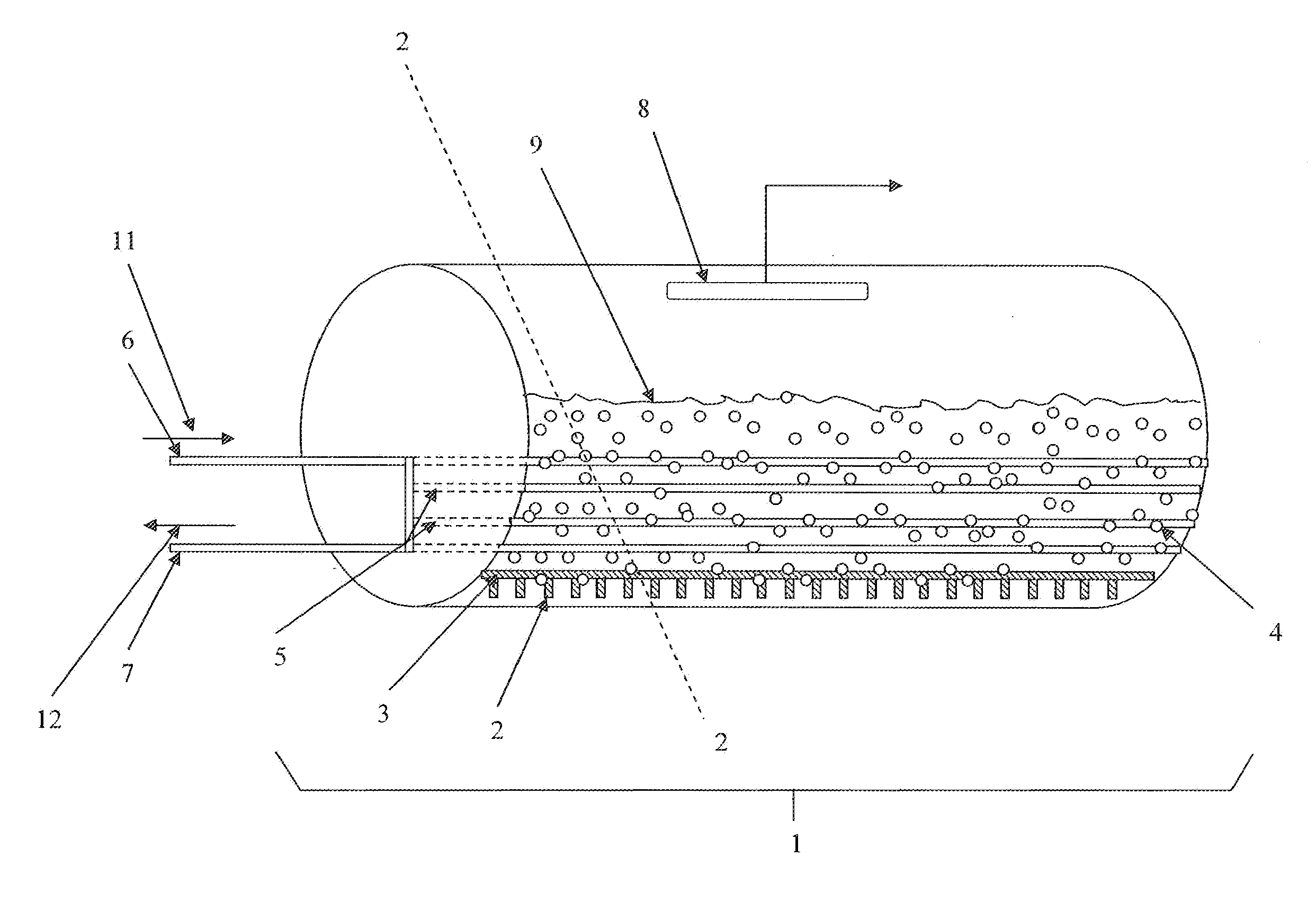
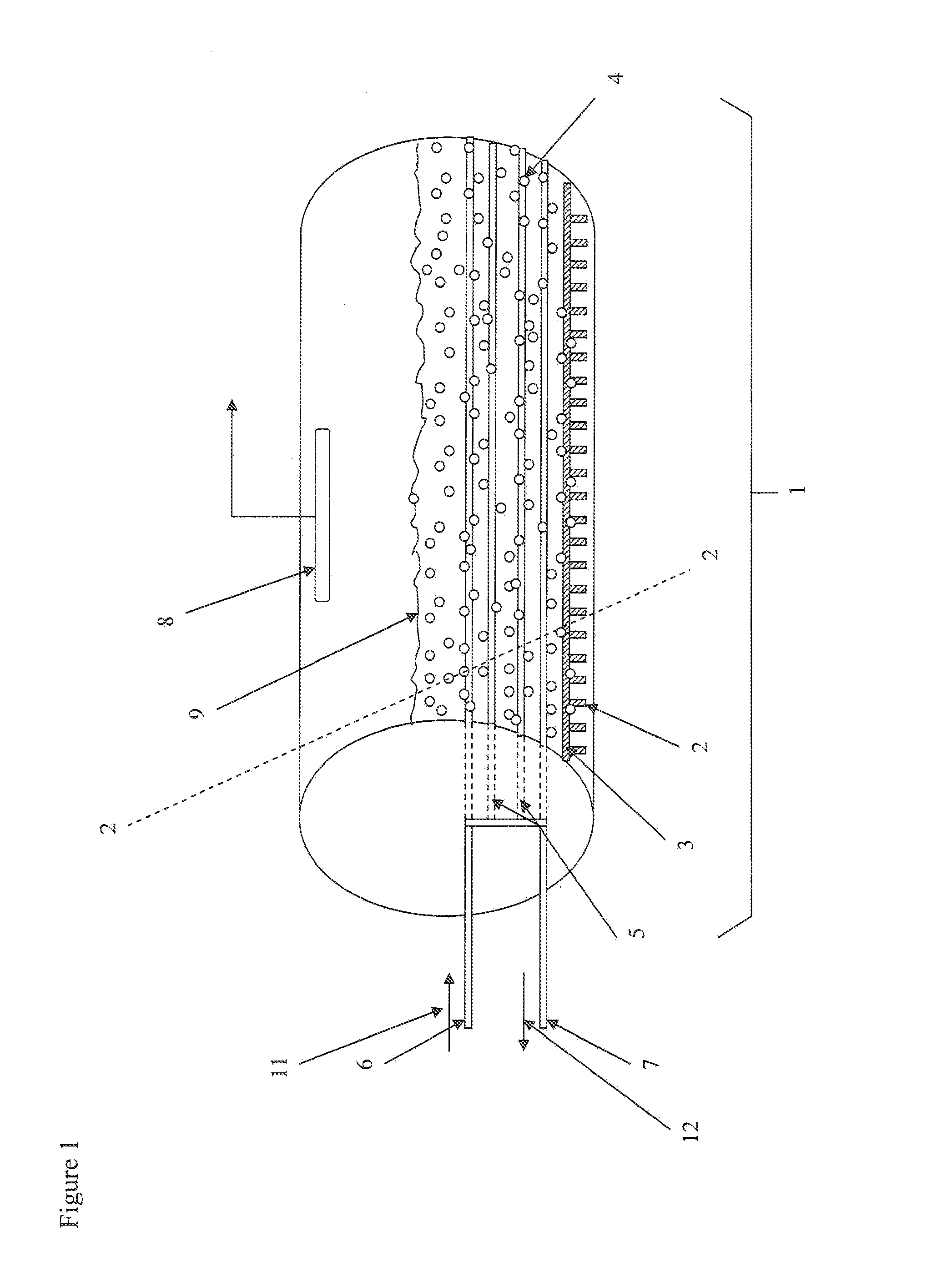
[0029]The present invention provides an assembly for a three phase slurry bubble column reactor for use in the Fischer-Tropsch process. Referring to the drawings in detail, FIG. 1 illustrates a perspective view of a three phase slurry bubble column reactor vessel according to the present invention. The reactor vessel is a closed container except as described herein. Synthesis gas is fed int...


PUM


Abstract

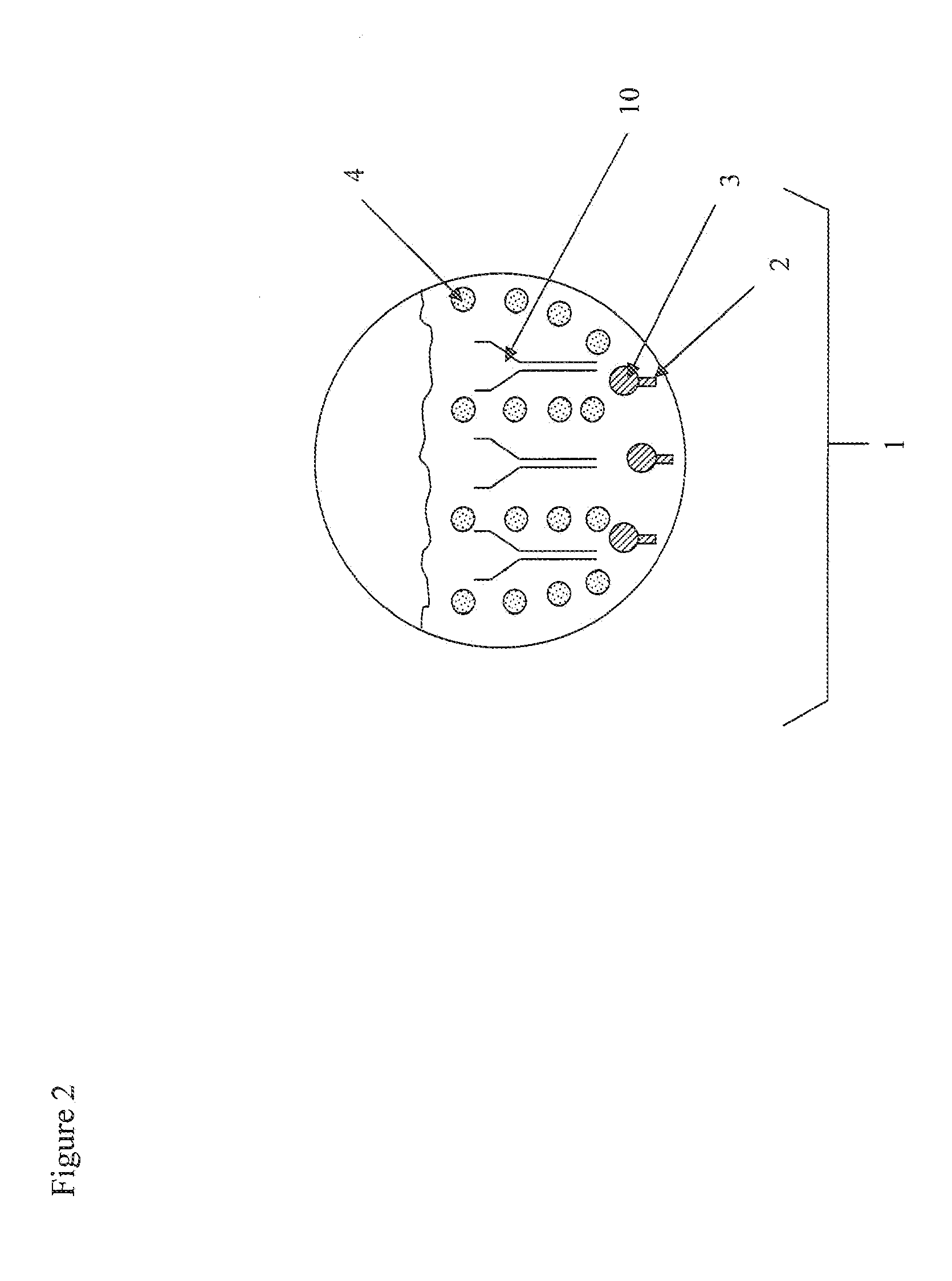
A reactor for carrying out a chemical reaction in a three phase slurry system providing a horizontal reaction vessel with a cross sectional area which is dependent on the vessel length, vessel diameter, and axial position. The vessel has a gas inlet at or near the bottom of the reaction vessel and a gas distributor. The gas product exits the vessel by conduit means at or near the top of the reaction vessel. The vessel includes a plurality of horizontal cooling coils to provide a cooling medium to the slurry. In the reaction vessel, the synthesis gas has an average linear velocity which is a function of the vessel cross sectional area.

Description

CROSS-REFERENCE TO RELATED APPLICATIONS[0001]This application claims priority to U.S. Provisional Application No. 61 / 374,194, filed Aug. 16, 2010, which is herein incorporated in its entirety by reference.BACKGROUND OF THE INVENTION[0002]1. Field of the Invention[0003]The present invention relates in general to a reactor and a process for the preparation of hydrocarbons from synthesis gas, typically known as the Fischer-Tropsch process. More particularly, this invention pertains to a three phase slurry bubble column reactor that can maximize the production rate per unit volume of the reactor.[0004]2. Prior Art[0005]The Fischer-Tropsch process is the second step of a two step process that converts natural gas to liquid fuels. The first step in the conversion process transforms carbonaceous feedstock such as natural gas, coal, petroleum coke, heavy oils, biomass, landfill gas, biogas and municipal waste into a synthesis gas comprised of carbon monoxide and hydrogen. The second step, w...

Claims


Application Information

Patent Timeline
Patent Type & Authority Applications(United States)
IPC IPC(8): B01J19/00
CPCB01J8/1827B01J8/1836B01J8/226B01J8/006B01J2219/182B01J2208/00141B01J2208/003B01J2208/0084B01J2208/00902C10G2/342
Inventor ESPINOZA, RAFAELAGEE, KENNETH L.
Owner EMERGING FUELS TECH
Learn More