Brake control device
- Summary
- Abstract
- Description
- Claims
- Application Information
AI Technical Summary
Benefits of technology
Problems solved by technology
Method used
Image
Examples
first embodiment
[0076]The first embodiment is described referring mainly to FIG. 5.
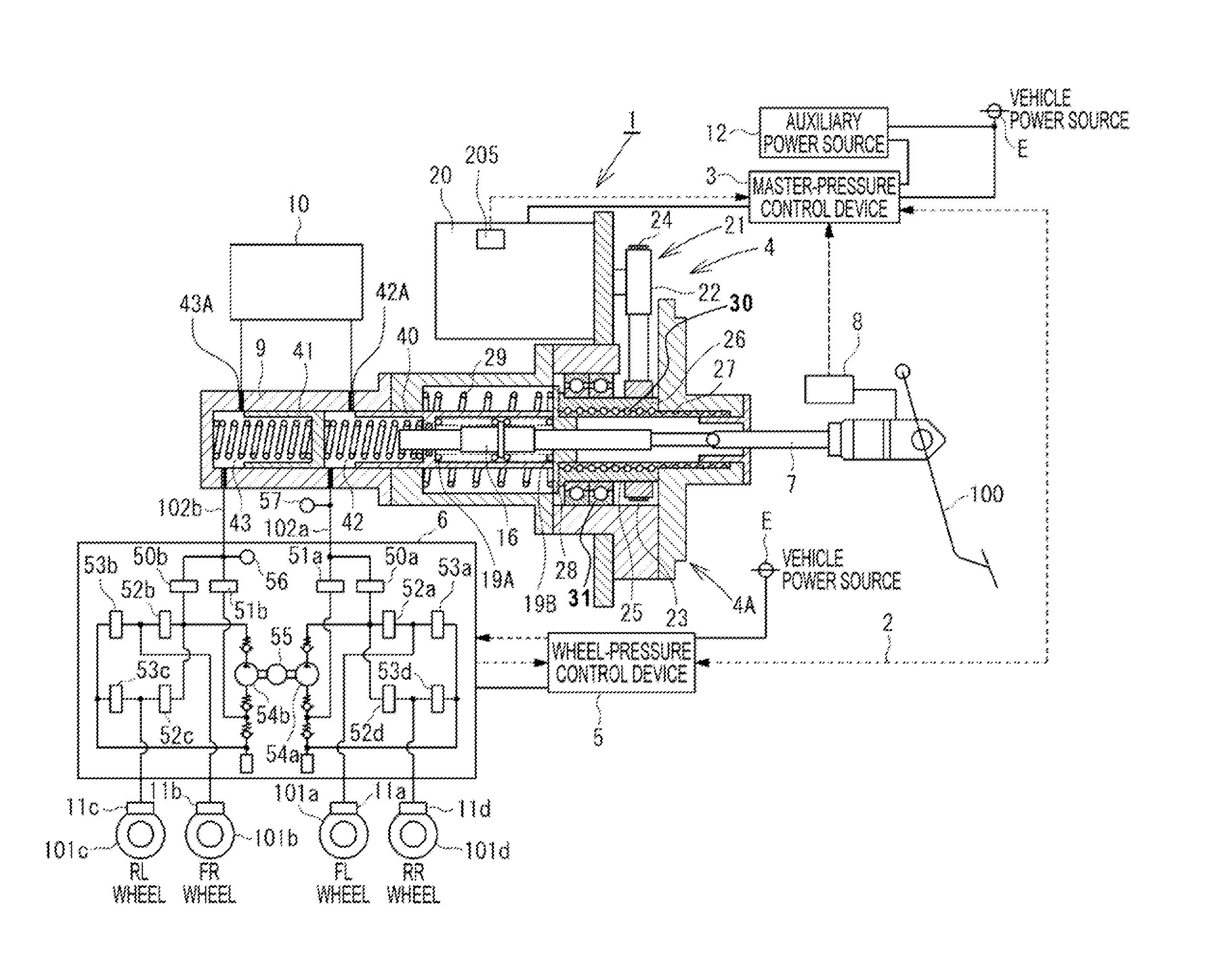
[0077]In the first embodiment, when the system end conditions are satisfied, the power-supply interruption control is executed to interrupt the vehicle power source E and supply the necessary electric power from the auxiliary power source 12. In this manner, the brake control is continued by the master-pressure control device 3 until the electric power stored in the auxiliary power source 12 is depleted.
[0078]An example of a control flow for executing the power-supply interruption control according to this embodiment is illustrated in FIG. 5. Referring to FIG. 5, in Step S50, it is determined whether or not the system end conditions have been satisfied. Then, when the system end conditions have not been satisfied, the processing proceeds to Step S51. Subsequently, in Steps S52 to S55, the same processing as that performed in Steps S11 to S15 illustrated in FIG. 3 is performed. When the vehicle power source E is norma...
second embodiment
[0082]In the second embodiment, when the system end conditions are satisfied, the power-supply interruption control is executed to interrupt the vehicle power source E and supply the necessary electric power from the auxiliary power source 12 when the amount of electric power (amount of charge) of the auxiliary power source 12 is equal to or larger than a given amount. In this manner, the brake control is continued by the master-pressure control device 3.
[0083]An example of a control flow for executing the power-supply interruption control according to this embodiment is illustrated in FIG. 6. Referring to FIG. 6, in Step S60, it is determined whether or not the system end conditions have been satisfied. Then, when the system end conditions have not been satisfied, the processing proceeds to Step S61. Subsequently, in Steps S62 to S65, the same processing as that performed in Steps S11 to S15 illustrated in FIG. 3 is performed. When the vehicle power source E is normal, the control ...
third embodiment
[0086]In the third embodiment, when the system end conditions are satisfied, the power-supply interruption control is executed to interrupt the vehicle power source E and supply the necessary electric power from the auxiliary power source 12. In this manner, the brake control is continued by the master-pressure control device 3 for a predetermined period of time.
[0087]An example of a control flow for executing the power-supply interruption control according to this embodiment is illustrated in FIG. 7. Referring to FIG. 7, in Step S70, it is determined whether or not the system end conditions have been satisfied. Then, when the system end conditions have not been satisfied, the processing proceeds to Step S71. Subsequently, in Steps S72 to S75, the same processing as that performed in Steps S11 to S15 illustrated in FIG. 3 is performed. When the vehicle power source E is normal, the control is performed in the normal control mode in Step S75. On the other hand, in a case of a failure...
PUM
 Abstract
Description
Claims
Application Information
 - R&D
- Intellectual Property
- Life Sciences
- Materials
- Tech Scout
- Unparalleled Data Quality
- Higher Quality Content
- 60% Fewer Hallucinations
Browse by: Latest US Patents, China's latest patents, Technical Efficacy Thesaurus, Application Domain, Technology Topic, Popular Technical Reports.
© 2025 PatSnap. All rights reserved.Legal|Privacy policy|Modern Slavery Act Transparency Statement|Sitemap|About US| Contact US: help@patsnap.com


