
Printed circuit board

a technology of printed circuit board and printed circuit, which is applied in the direction of printed circuit assembling, printed circuit non-printed electric components association, high frequency circuit adaptation, etc., can solve the problems of signal loss, transmission power reduction, and limit the use of mass-production equipment in order to lower the thickness of the core material, so as to improve signal transmitting characteristics, high density wiring, and slim thickness

Inactive Publication Date: 2013-04-04
SAMSUNG ELECTRO MECHANICS CO LTD
View PDF5 Cites 2 Cited by
  • Summary
  • Abstract
  • Description
  • Claims
  • Application Information

AI Technical Summary

Benefits of technology

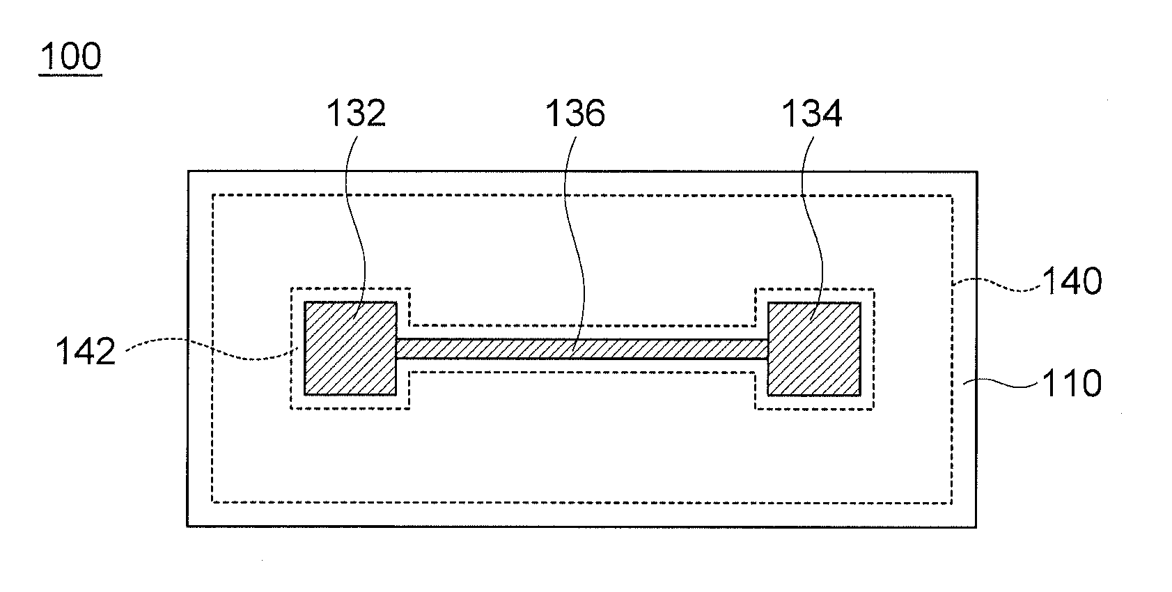
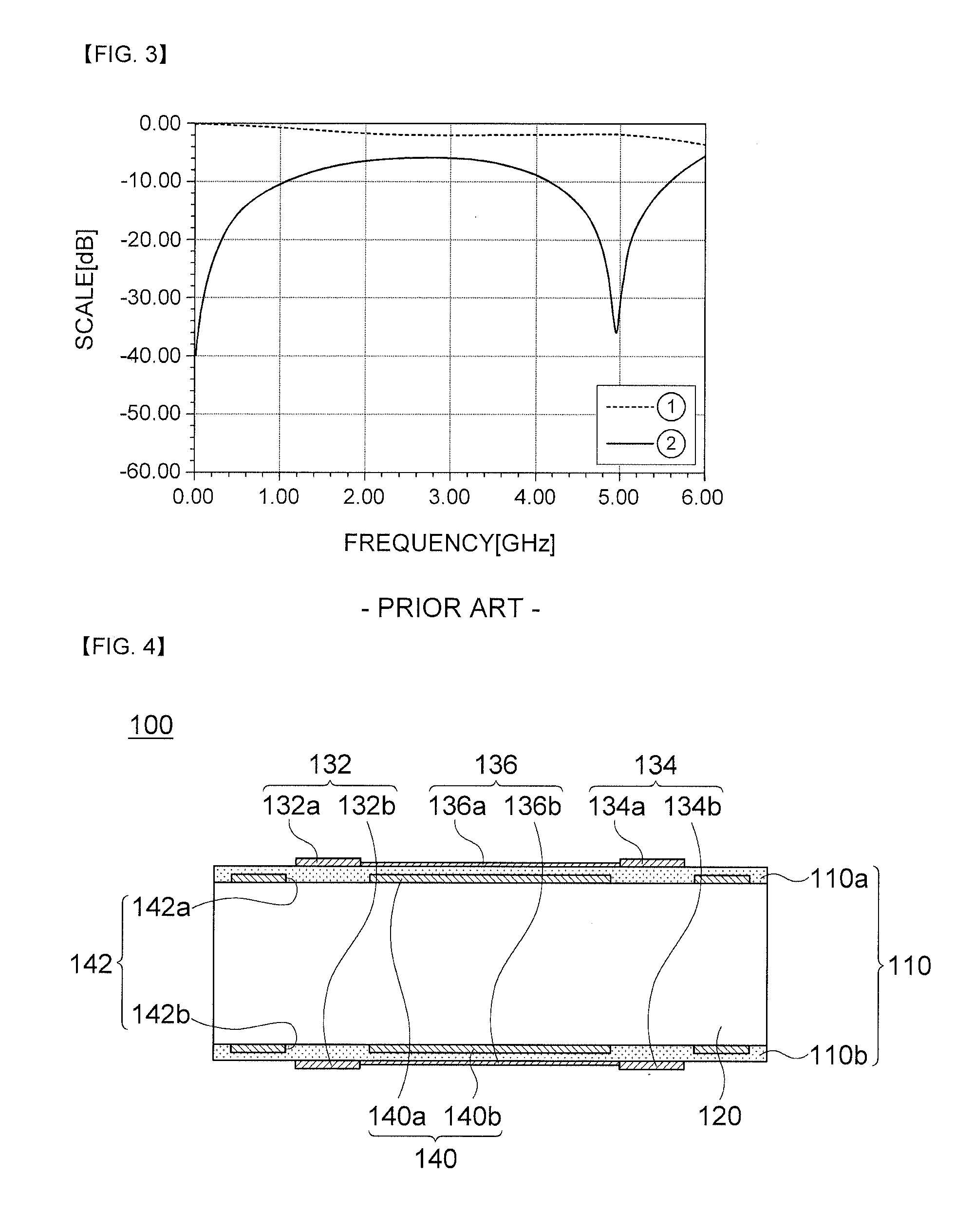
The present invention provides a printed circuit board that allows for high-density wiring and slim thickness. This is achieved by forming slots in partial regions of the ground surface facing pads, which improves signal transmitting characteristics.

Problems solved by technology

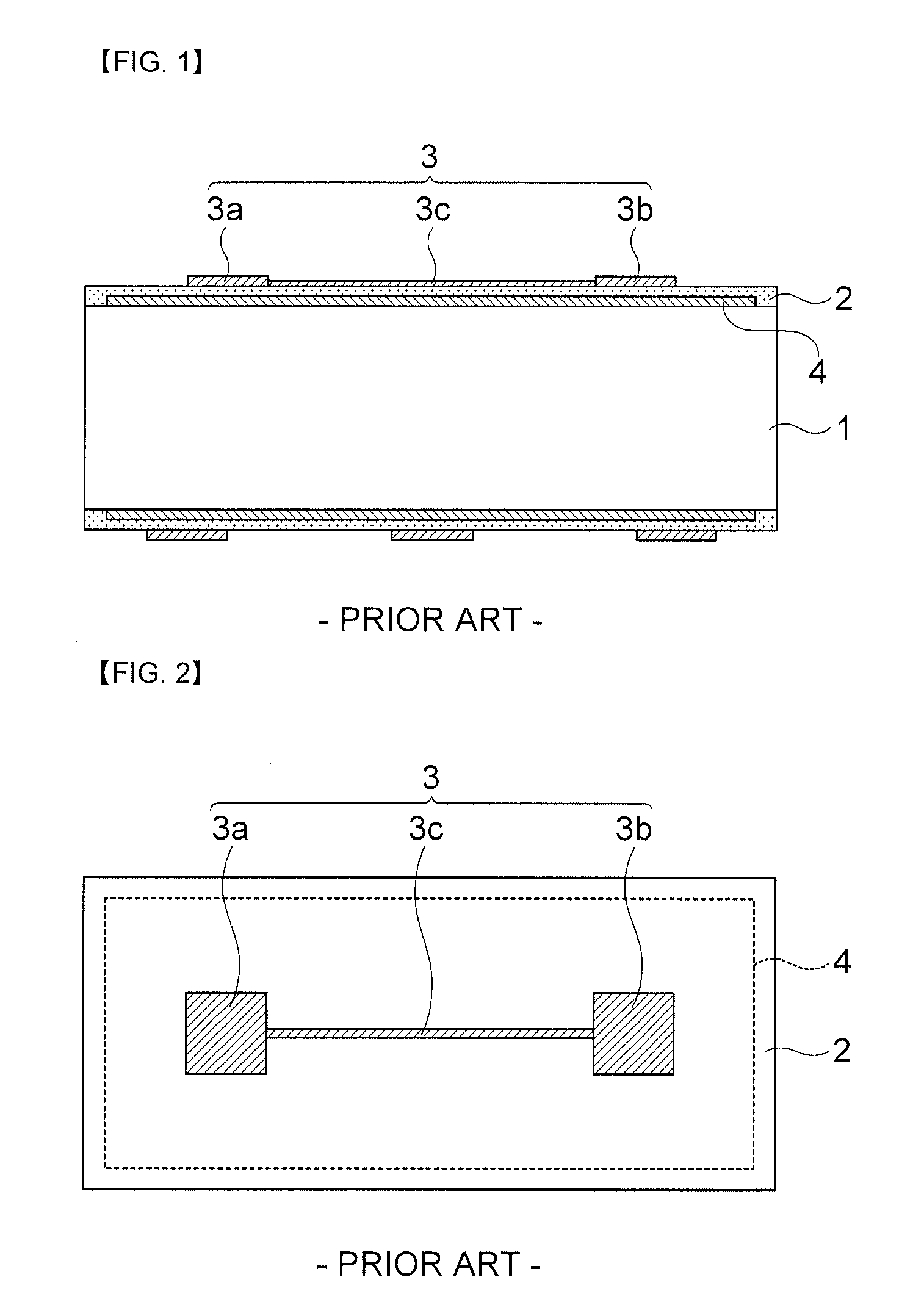
However, there is a limitation in driving using mass-production equipment in order to lower the thickness of the core material.
Therefore, when the printed circuit board of the related art is used to embody a module or a system, transmission power is reduced in a signal transmitter and a signal receiving sensitivity is deteriorated in a signal receive, which is caused by an increase in signal loss, resulting in deterioration in performance of the entire system.

Method used


Image

  • Printed circuit board
  • Printed circuit board
  • Printed circuit board

Examples


Embodiment Construction

[0041]Terms and words used in the present specification and claims are not to be construed as a general or dictionary meaning but are to be construed meaning and concepts meeting the technical ideas of the present invention based on a principle that the inventors can appropriately define the concepts of terms in order to describe their own inventions in the best mode.

[0042]Therefore, the configurations described in the embodiments and drawings of the present invention are merely most preferable embodiments but do not represent all of the technical spirit of the present invention. Thus, the present invention should be construed as including all the changes, equivalents, and substitutions included in the spirit and scope of the present invention at the time of filing this application.

[0043]Hereinafter, embodiments of the present invention will be described with reference to the accompanying drawings.

[0044]FIG. 4 is a cross-sectional view of a printed circuit board according to one exe...


PUM


Abstract

Disclosed herein is a printed circuit board, including: a dielectric substrate having a ground surface; a plurality of pads formed on the dielectric substrate; a transmission line transmitting a signal between the plurality of pads; and slots formed in partial regions of the ground surface correspondingly to the pads, thereby to improve signal transmitting characteristics and allow high-density wiring and thin thickness.

Description

CROSS REFERENCE(S) TO RELATED APPLICATIONS[0001]This application claims the benefit under 35 U.S.C. Section 119 of Korean Patent Application Serial No. 10-2011-0099537, entitled “Printed Circuit Board” filed on Sep. 30, 2011, which is hereby incorporated by reference in its entirety into this application.BACKGROUND OF THE INVENTION[0002]1. Technical Field[0003]The present invention relates to a printed circuit board including transmission lines transmitting signals between a plurality of pads and a plurality of pads, and more particularly to a printed circuit board capable of improving signal transmitting characteristics by removing parasitic components generated between the pads and the transmission lines.[0004]2. Description of the Related Art[0005]In accordance with the recent development of the electronic industry, the demand for multi-functional and slim and light electronic components has rapidly increased. Therefore, a printed circuit board having the electronic components mo...

Claims


Application Information

Patent Timeline
Patent Type & Authority Applications(United States)
IPC IPC(8): H05K1/11
CPCH05K1/0225H05K1/0253H05K1/111H05K1/18H05K1/02H05K3/32
Inventor LEE, DONG HWANPARK, SEUNG WOOKLIM, KYUNG SANGKWEON, YOUNG DO
Owner SAMSUNG ELECTRO MECHANICS CO LTD
Learn More