Optical observation device with at least one visual observation beam path

a technology of optical observation and beam path, which is applied in the field of optical observation devices with at least one visual observation beam path, can solve the problems of often requiring a larger space than the actual basic prism system, and achieve the effect of less physical space for the inward reflection module and high transmission of the observation beam path

Inactive Publication Date: 2013-03-28
CARL ZEISS SMT GMBH
View PDF5 Cites 9 Cited by
  • Summary
  • Abstract
  • Description
  • Claims
  • Application Information

AI Technical Summary

Benefits of technology

[0009]Starting therefrom, it is the object of the present invention to improve an optical observation device of the type mentioned at the beginning, the aim, in particular, being to achieve a lesser demand on physical space for the inward reflection module, as well as a high transmission of the observation beam path.
[0011]Owing to the fact that the Abbe König prism system, the Porro prism system or the Schmidt Pechan prism system is provided with the at least one holographic optical element of the at least one device for image superposition, a beam splitter and an imaging optics which may be necessary are advantageously combined in a hologram that can be introduced at a suitable point in the prism system. In this case, the hologram ensures that an, in particular monochromatic, display is coupled in and, optionally, that the image of the display is additionally imaged in the observation beam path. This reduces the requisite physical space substantially and simplifies installation. Owing to the narrow bandwidth of the coupling in, particularly in a region of less than 100 nm, in particular less than 50 nm, preferably less than 20 nm, the transmission of the residual wavelengths in the observation beam path is only slightly disturbed, and the total transmission of the visual observation beam path becomes much higher than in the case of the known solutions.
[0012]The holographic optical element can effect a deflection of the light, which is to be superposed, of the image of the display device in the at least one visual observation beam path.
[0013]It is advantageous when the holographic optical element additionally effects an imaging, a collimation and / or a wavelength selection of the light, which is to be superposed, of the display device.
[0014]The integration and / or combination of the different optical elements with their effects in a hologram reduces the requisite physical space and substantially simplifies installation. The basis for the hologram is provided by an optics consisting, at least, of a first prism, an optional collimator that images the display onto an image plane and an optional further prism that can determine the installation angle of the display. The first prism should have an angle such that, were the prism cemented on the face of the inverting prism system, light can be incident in the prism system from the display. If required, it would, of course, be possible for yet further optical elements to be integrated, for example in order to enlarge or reduce the imaging.
[0016]It is advantageous when the holographic optical element is applied as a holographic layer to a face of the Abbe König prism system, of the Porro prism system or of the Schmidt Pechan prism system.

Problems solved by technology

Such known solutions frequently require a greater space than the actual basic prism system.

Method used


Image

  • Optical observation device with at least one visual observation beam path
  • Optical observation device with at least one visual observation beam path
  • Optical observation device with at least one visual observation beam path

Examples


first embodiment

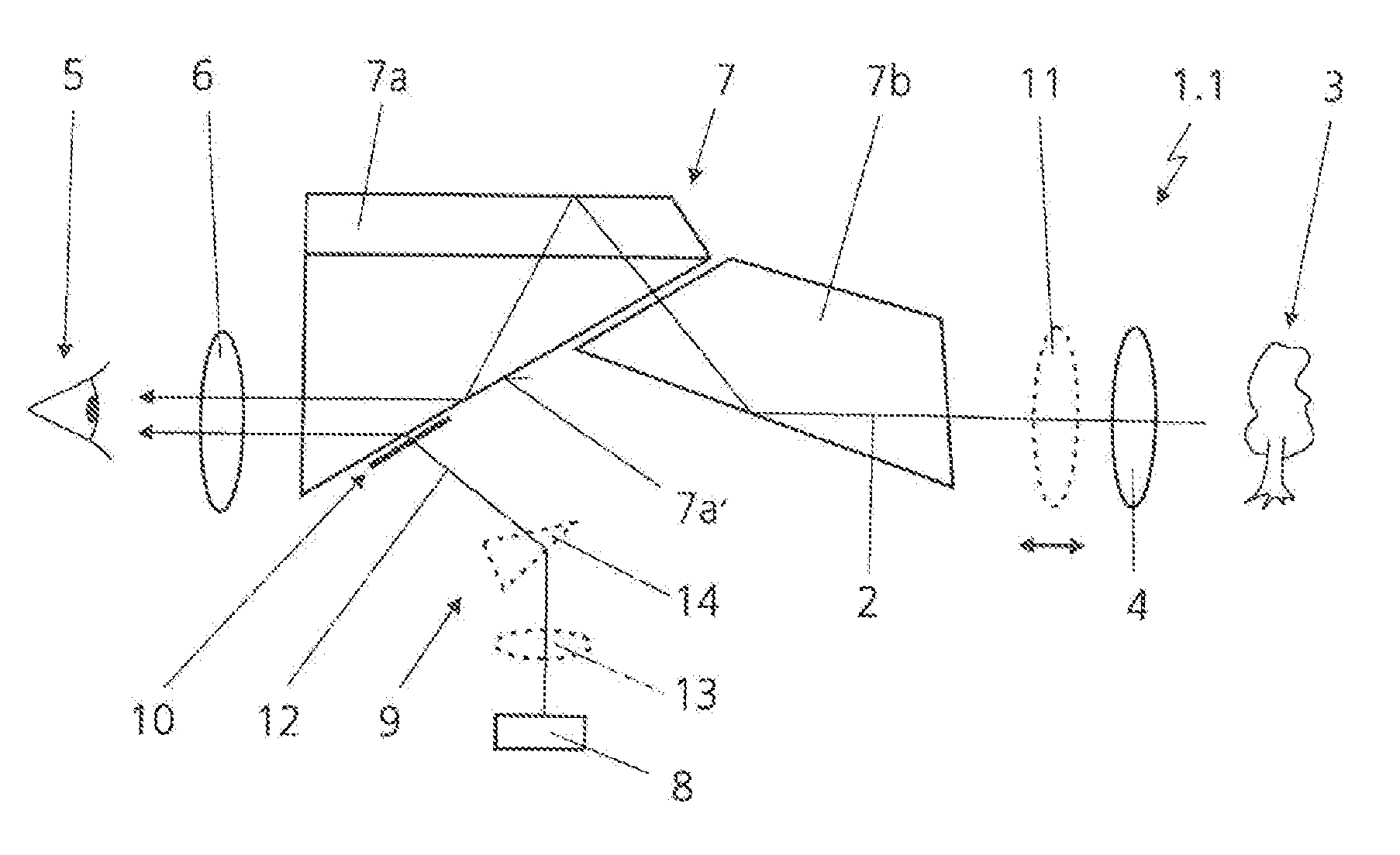
[0039]FIG. 1 illustrates an inventive optical observation device 1.1 in a first embodiment with a visual observation beam path 2 which has an objective lens 4, that is to be turned in an operating position to a target object 3 to be observed and images the target object 3, and an eyepiece 6 that is to be turned to an eye 5 of an observer. An Abbe König prism system 7 for imaging version of the visual observation beam path 2 is arranged in the visual observation beam path 2 between the objective lens 4 and the eyepiece 6. The Abbe König prism system 7 has a roof prism 7a and an isosceles prism 7b. As regards further details of the Abbe König prism system 7, reference is made to DE 10 2008 003 414 A1 quoted at the beginning, which likewise discloses binoculars with an Abbe König prism system. For reasons of space, in particular, the roof prism 7a is frequently arranged in the direction of the eyepiece 6 in the visual observation beam path 2. In addition, the roof prism 7a is then loca...

second embodiment

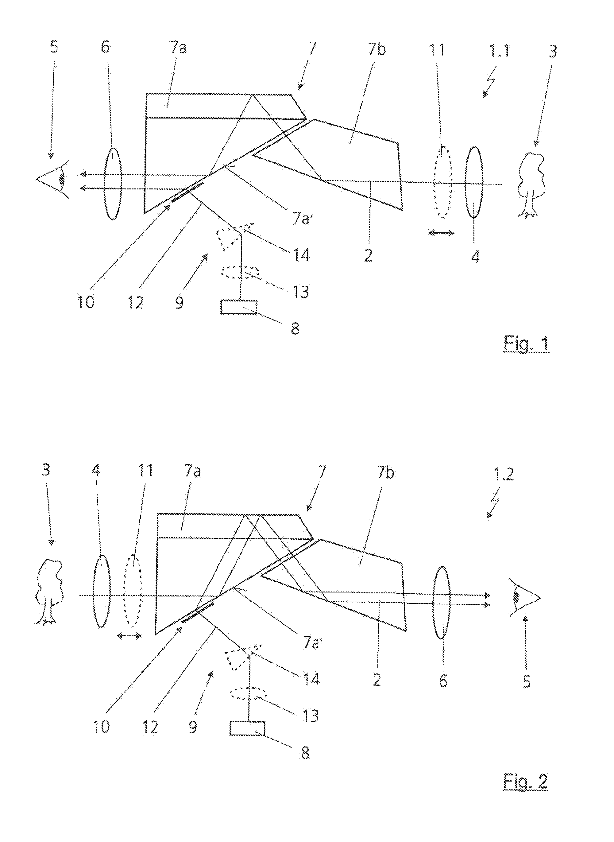
[0048]an inventive optical observation device 1.2 is illustrated in FIG. 2. Here, the Abbe König prism system 7 is arranged inverted in the optical observation device 1.2, that is to say that the roof prism 7a is not turned to the eye 5 of the observer, but to the objective lens 4 or the target object 3.

[0049]The holographic layer 10 can be applied directly to the face 7a′ of the roof prism 7a by direct exposure of a photosensitive layer such as, for example, silver salt. Furthermore, it is possible to introduce the holographic layer 10 into the face 7a′ of the roof prism 7a as a laser engraving. The holographic layer 10 can also be produced as a plastic pressed hologram or in another, generally known technique for holographic fabrication.

third embodiment

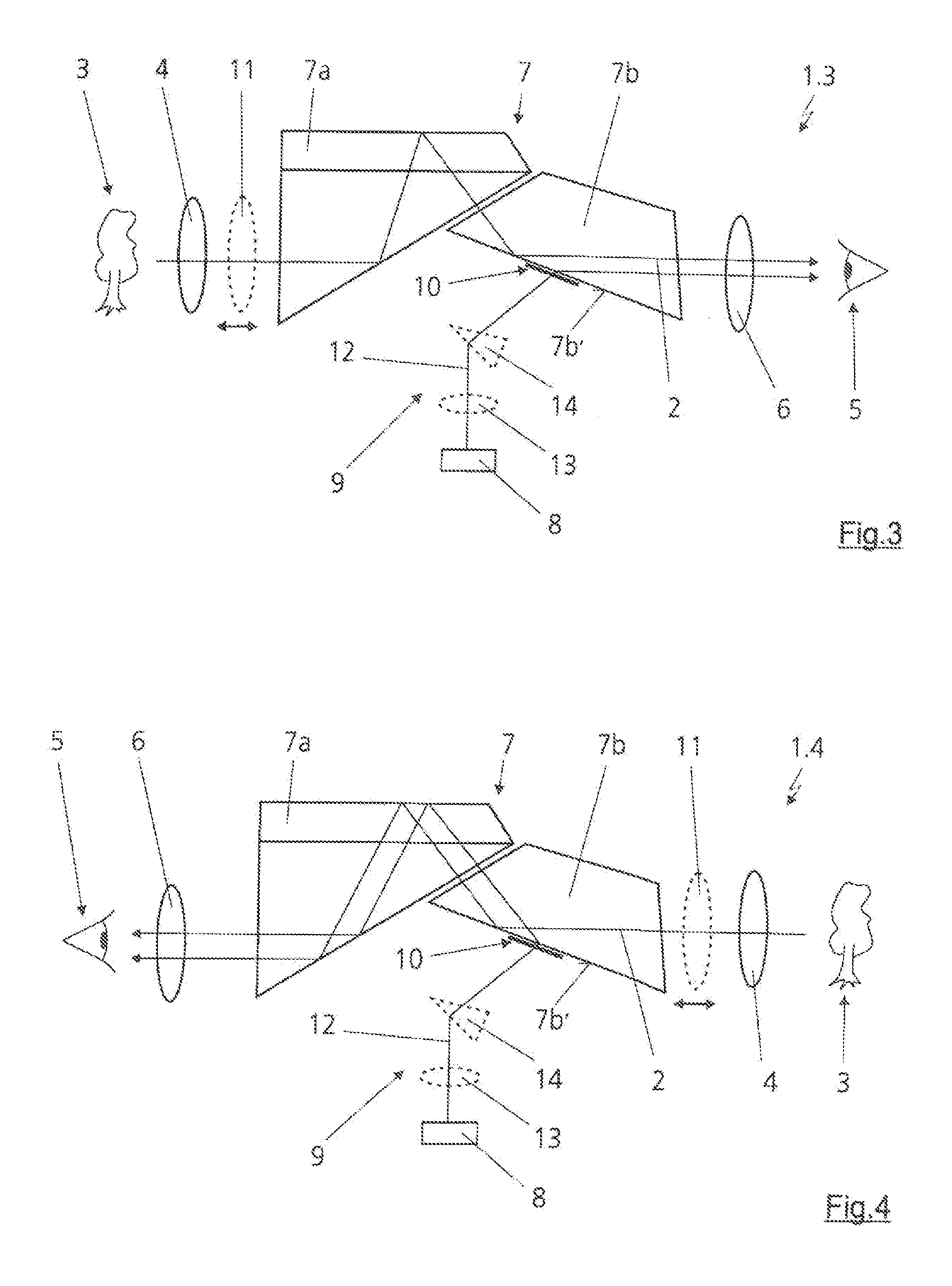
[0050]FIG. 3 illustrates an inventive optical observation device 1.3. The holographic layer 10 is applied in this case to a face 7b′ of the isosceles prism 7b of the Abbe König prism system 7.

[0051]FIG. 4 shows a fourth embodiment of an inventive optical observation device 1.4. By contrast with the third embodiment of the inventive optical observation device 1.3 from FIG. 3, in this case it is only the Abbe König prism system 7 that is arranged in an inverted fashion, and so the roof prism 7a is turned to the eye 5 of the observer.


PUM


Abstract

An optical observation device with at least one visual observation beam path, includesan objective lens,an eyepiece,an Abbe König prism system, Porro prism system or Schmidt Pechan prism system, arranged in the at least one visual observation beam path between the objective lens and the eyepiece,a display device for displaying an additional image in the visual observation beam path to the observer, anda device for image superposition, which has a holographic optical element, and which uses the holographic optical element to superpose onto the image of the display device the image of a target object to be observed in an intermediate image plane of the visual observation beam path.The prism system is provided with the at least one holographic element of the at least one device for image superposition.

Description

CROSS-REFERENCE TO RELATED APPLICATIONS[0001]This application claims priority under 35 U.S.C. §119(a)-(d), to German Application No. 10 2011 005 229.1, filed Mar. 8, 2011. The foregoing application is expressly incorporated herein by reference in its entirety to form part of the present disclosure.FIELD OF THE INVENTION[0002]The invention relates to an optical observation device with at least one visual observation beam path in accordance with the preamble of claim 1.[0003]In optical observation devices such as aiming op-tics, telescopes, microscopes or the like, it should be possible for information and / or data, flexible target markers etc. to be displayed or superposed for the user. Different superposition and / or inward reflection concepts are known from practice for this purpose. Such optical inward reflection methods should substantially fulfill the following boundary conditions. The transmittance for the main light and / or the observation light of the optical observation device ...

Claims


Application Information

Patent Timeline
Patent Type & Authority Applications(United States)
IPC IPC(8): G02B27/01
CPCG02B5/04G02B5/32G02B27/0103G02B21/00G02B23/10G02B17/04
Inventor BACH, CHRISTIAN
Owner CARL ZEISS SMT GMBH
Why Eureka
Try Eureka