
Hollow fiber apparatus and use thereof for fluids separations and heat and mass transfers

a technology of fluid separation and fiber, applied in the field of hollow fiber apparatus, can solve problems such as premature device failure, and achieve the effects of reducing the overall weight and size of the apparatus, and increasing thermal and mechanical stability

Active Publication Date: 2013-03-21
MASSACHUSETTS DEV FINANCE AGENCY +1
View PDF1 Cites 28 Cited by
  • Summary
  • Abstract
  • Description
  • Claims
  • Application Information

AI Technical Summary

Benefits of technology

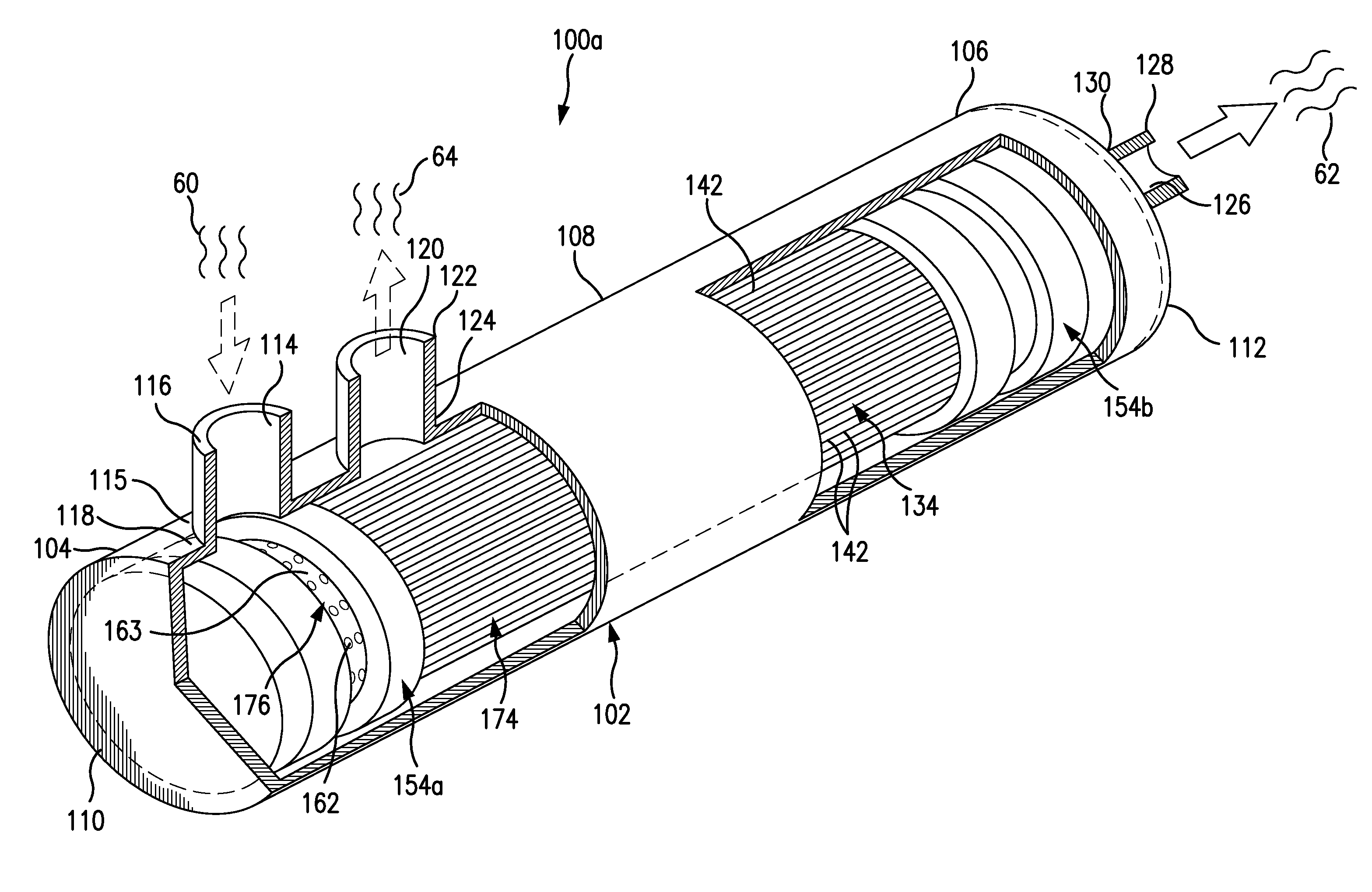
This patent describes an improved design for hollow fiber devices that can operate with high pressure differences between the bore and shell side without tubesheet failure. This design also reduces or minimizes problems with existing tubesheets, making it possible to operate at elevated temperatures and pressures in various applications such as fluid separation and heat transfer. The design features maximized bore holes for fluid ingress and egress and a redistribution of the load on the tubesheets to increase operational capabilities. The devices are compact, light weight, and stable at high temperatures and pressures, making them efficient and effective in transportation applications. This design also provides increased fuel savings over conventional heat exchangers.

Problems solved by technology

This need is particularly critical for fluid separation and heat transfer and mass transfer applications that require high temperature process conditions, e.g., in access of 70° C., where creep of tubesheet materials is accelerated, leading to a premature device failure.

Method used


Image

  • Hollow fiber apparatus and use thereof for fluids separations and heat and mass transfers
  • Hollow fiber apparatus and use thereof for fluids separations and heat and mass transfers
  • Hollow fiber apparatus and use thereof for fluids separations and heat and mass transfers

Examples


Embodiment Construction

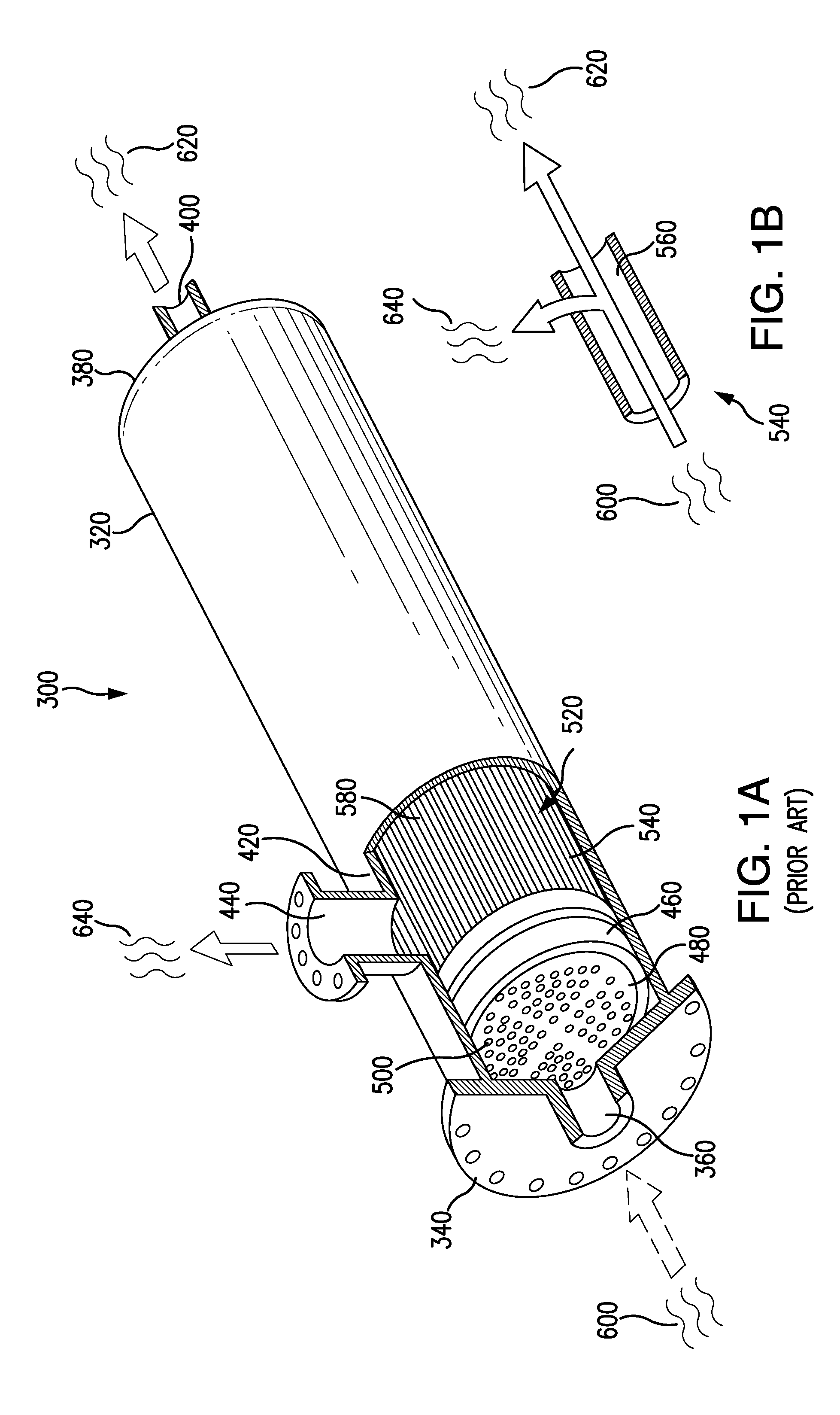
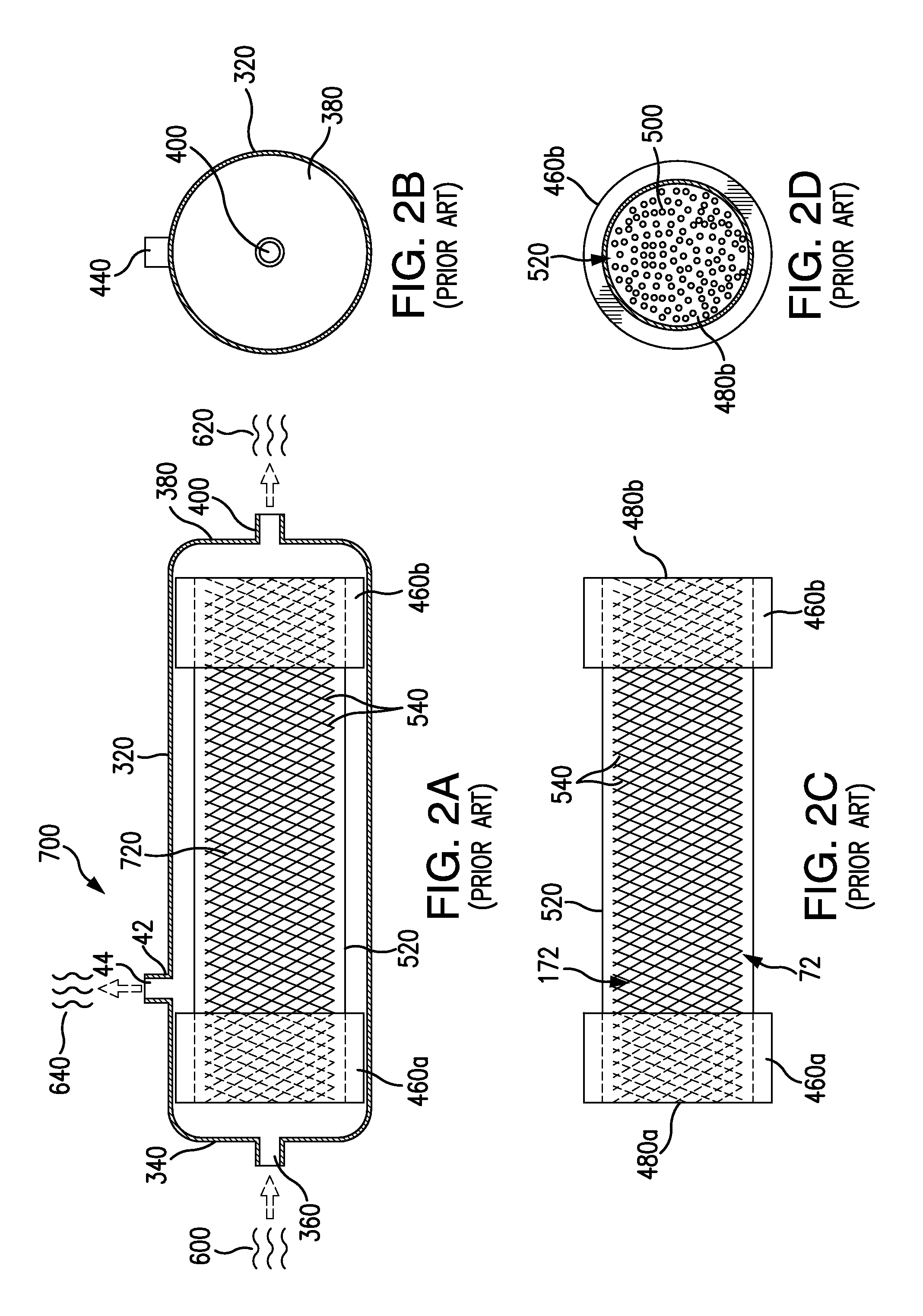
[0044]The invention generally utilizes hollow fibers, which are small diameter tubes, typically below 5 mm in diameter. These hollow fibers are configured into a hollow fiber device (also referred to herein as a cartridge), the cartridge is housed in an enclosure that can be a pressure vessel, and the combined assembly is frequently referred to as a module. The module can be used as a heat or heat and mass exchange apparatus in a heat or heat and mass transfer process or as a fluid separation device.

[0045]Hollow fiber devices can be thought of as a subset of tubular devices and provide for a high surface area in a given volume which is an advantageous, compact packaging configuration. The device can be elongated in shape, for instance cylindrical or nearly cylindrical, with hollow fibers, typically in a hollow fiber bundle, being arranged around a central core member that in some embodiments serves as a fluid introduction / withdrawal conduit.

[0046]In many cases, the core member is tu...


PUM

PropertyMeasurementUnit
Angleaaaaaaaaaa
Angleaaaaaaaaaa
Diameteraaaaaaaaaa

Abstract

A hollow fiber device includes a hollow fiber bundle, comprising a plurality of hollow fibers, a first tubesheet and a second tubesheet encapsulating respective distal ends of the hollow fiber bundle. The tubesheets have boreholes in fluid communication with bores of the hollow fibers. In at least one of the tubesheets, the boreholes are formed radially. The hollow fiber device can be utilized in heat exchange, in gas / gas, liquid / liquid and gas / liquid heat transfer, in combined heat and mass transfer and in fluid separation assemblies and processes. The design disclosed herein is light weight and compact and is particularly advantageous when the pressure of a first fluid introduced into the bores of hollow fibers is higher than the pressure on the shell side of the device.

Description

RELATED APPLICATIONS[0001]This application is a Continuation-in-Part of U.S. application Ser. No. 13 / 411,548, with the title Fluid Separation Assembly and Method, filed on Mar. 3, 2012, under Attorney Docket No. 11-0135-US-NP, which claims the benefit under 35 USC 119(e) of U.S. Provisional Application No. 61 / 494,867, with the title Fluid Separation Assembly and Method, filed on Jun. 8, 2011, under Attorney Docket No. 11-0135-US-PSP, both of which are incorporated herein by reference in their entirety.STATEMENT REGARDING FEDERALLY SPONSORED RESEARCH OR DEVELOPMENT[0002]This invention was made with government support under Contract No. DE-SC000336 awarded by the Department of Energy (DOE). The government has certain rights in the invention.BACKGROUND OF THE INVENTION[0003]Hollow fiber devices are used extensively in separation of fluids both gases and liquids, in mass transfer applications such as adding or removing a gas to or from a liquid that involve transfer of the gas through a...

Claims


Application Information

Patent Timeline
IPC IPC(8): F28D15/00F28F1/00
CPCB01D53/228Y10T428/139F28F21/062F28D21/0015F28F1/00Y10T428/1393F28D7/1669F28D2021/0021F28D15/00F28F9/026B01D2313/12B01D1/22Y02T50/44B01D63/02B01D2313/10F28D7/024B64D37/32B01D53/22B01D63/022B01D63/025B01D2315/10B01D2325/022Y02T50/40B01D2313/221B01D63/0233
Inventor BIKSON, BENJAMINETTER, STEPHENCHING, NATHANIEL
Owner MASSACHUSETTS DEV FINANCE AGENCY
Learn More