
Microfluidic device with multilayer coating

a microfluidic device and multi-layer coating technology, applied in the field of microfluidic devices, can solve the problems of insufficient film employed for the purpose and achieve the effects of improving the performance enhancing the reliable operation of the microfluidic device or component, and minimizing the number of defects presen

Active Publication Date: 2013-03-14
EASTMAN KODAK CO
View PDF10 Cites 68 Cited by
  • Summary
  • Abstract
  • Description
  • Claims
  • Application Information

AI Technical Summary

Benefits of technology

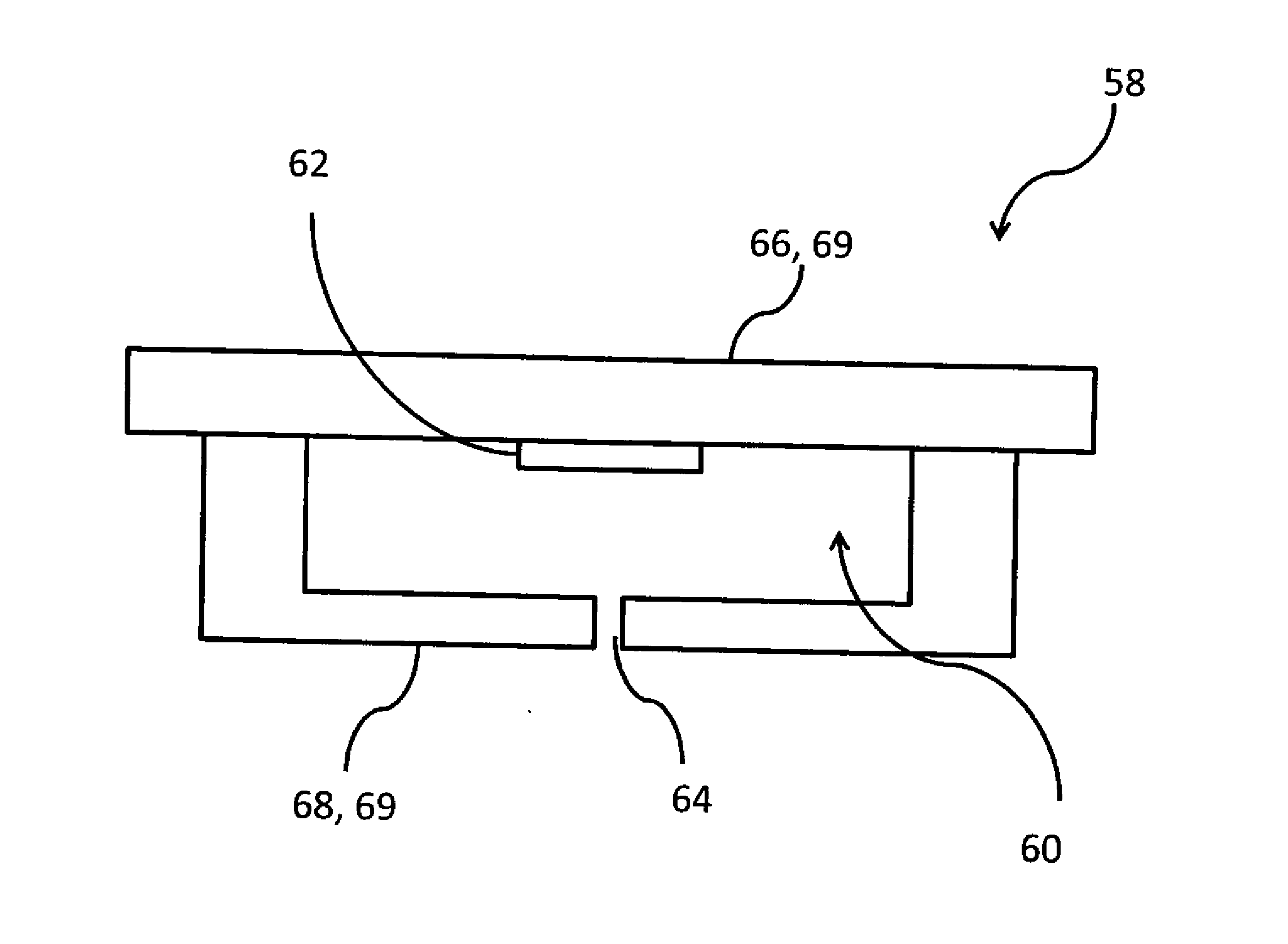
The present invention provides a microfluidic device comprised of a material layer and a fluid transport feature having at least one characteristic dimension of less than 500 micrometers formed in or on the material layer, that is substantially improved in chemical resistance, thermally stability, and biocompatibility. The invention achieves this by providing a chemically resistant, thermally stable, and biocompatible multilayer coating onto and in contact with the microfluidic device. The corrosion resistant film employed in the invention can be formed on the surfaces of fluid transport features of microfluidic devices using film forming methods that produce conformal films that cover complex geometries, thereby enabling the corrosion resistant film to be formed on all surfaces of the fluid transport features of the microfluidic device that come in contact with reactants, analytes, inks or other fluids employed in the microfluidic device.

Problems solved by technology

It is not sufficient that a film employed for the purpose of improving the performance of a microfluidic device be chemically inert and biocompatible as in the case of hafnium metal, hafnium oxide, zirconium metal, zirconium oxide, tantalum metal, and tantalum oxide.
If these films or coatings have porosity or defects, these defects will influence the chemical purity of any fluid contacting the surface of the film because species from the fluid can diffuse into these defects.

Method used


Image

  • Microfluidic device with multilayer coating
  • Microfluidic device with multilayer coating
  • Microfluidic device with multilayer coating

Examples


example 1a-1f

[0092]This example demonstrates the use of an adhesion promoting layer in combination with an improved corrosion resistant laminate film comprised of multiple layers each consisting essentially of HfO2 or Ta2O5, and demonstrates at least one preferred composition of a corrosion resistant laminate as described in the invention. This example also demonstrates that the relative thickness, order and number of the refractory oxide layers in the invention is important with regard to achieving optimal results, and that the observed improved corrosion resistance of the laminate films, and in particular of hafnium oxide rich HfO2—Ta2O5 laminate films, is novel and could not have been predicted.

[0093]In examples 1A-1F the 200 nm of silicon oxide layer of the silicon wafer substrate described above is an adhesion promoting layer that enables corrosion resistant surface coatings and films that are deposited on top of the silicon wafer to adhere well to the wafer substrate. The outermost layer o...

example 2

[0097]This example demonstrates the use a wear and abrasion resistant coating on a chemically resistant, corrosion resistant laminate film as described in an embodiment of the invention.

[0098]Two silicon wafers with multilayer corrosion resistant films identical to example 1C were fabricated and one of the wafers was overcoated with 400 nm of an abrasion resistant coating containing silicon, nitrogen, and carbon at 320° C. The overcoat film containing silicon, nitrogen and carbon was prepared by chemical vapor deposition methods like those described by Bau et al (S. Bau, S. Janz, T. Kieliba, C. Schetter, S. Reber, and F. Lutz; WCPEC3-conference, Osaka, May 11-18 (2003); “Application of PECVD-SiC as Intermediate Layer in Crystalline Silicon Thin-Film Solar Cells”). The 200 nm of silicon oxide layer on the silicon wafer substrate is an adhesion promoting layer that is at least 0.2 nm in thickness and enables corrosion resistant surface coatings and films that are deposited on top of t...

example 3

[0099]This example demonstrates the use of an adhesion promoting layer in combination with a corrosion resistant laminate films comprised of multiple layers each consisting essentially of ZrO2 or Ta2O5. This example also demonstrates corrosion resistant laminate films where a thin film layer of ZrO2 is substituted for HfO2 in the laminate and where HfO2 and ZrO2 are both present as thin films in a laminate structure along with Ta2O5. In addition, this example demonstrates at least one additional preferred composition of a corrosion resistant laminate as described in the invention.

[0100]The outermost layer of the wafer substrates in examples 3A-3E, comprised of a SiO2 adhesion promoting layer, was then coated with a corrosion resistant film. Various types of corrosion resistant films were deposited for evaluation and the various films are given in examples 3A through 3E. Films in examples 3A-3E were deposited by atomic layer deposition methods using the methods described by Liu et al...


PUM

PropertyMeasurementUnit
thicknessaaaaaaaaaa
total thicknessaaaaaaaaaa

Abstract

A microfluidic device comprised of a material layer and a fluid transport feature having at least one characteristic dimension of less than 500 micrometers formed in or on the material layer. A chemically resistant, thermally stable and biocompatible multilayer coating is provided onto and in contact with the microfluidic device, wherein the multilayer coating includes one or more thin film layers comprised primarily of hafnium oxide or zirconium oxide and one or more thin film layers comprised primarily of tantalum oxide, the multilayer coating being located on a surface of the fluid transport feature. The corrosion resistant film can be formed on the surfaces of fluid transport features of microfluidic devices using atomic layer deposition film forming methods that produce conformal films that cover complex geometries, thereby enabling the corrosion resistant film to be formed on all surfaces of the fluid transport features of the microfluidic device.

Description

CROSS-REFERENCE TO RELATED APPLICATIONS[0001]Reference is made to commonly assigned U.S. patent Ser. No. ______ (Kodak Docket 96716) filed concurrently herewith, directed towards “Printhead for Inkjet Printing Device,” the disclosure of which is incorporated by reference herein in its entirety.FIELD OF THE INVENTION[0002]This invention relates generally to the field of microfluidic devices, and in particular to microfluidic devices where chemically resistant thin film layers are applied to fluid transport features of the microfluidic device.BACKGROUND OF THE INVENTION[0003]Microfluidic technologies refers to a set of technologies that control the flow of minute amounts of liquids or gases through fluid transport features having small characteristic dimensions, such that the volume of fluid flowing through the transport feature is typically measured in nanoliters and picoliters. Microfluidic devices comprise a large diverse class of devices employing microfluidic technologies for the...

Claims


Application Information

Patent Timeline
Patent Type & Authority Applications(United States)
IPC IPC(8): B32B3/10B32B3/30
CPCB41J2/14129Y10T428/24612Y10T428/24322
Inventor SIEBER, KURT D.
Owner EASTMAN KODAK CO
Learn More