
Tower frame combined transmitting pumping unit without guiding wheels

a transmission pumping unit and tower frame technology, applied in the direction of piston pumps, positive displacement liquid engines, wellbore/well accessories, etc., can solve the problems of limiting the wide promotion and application, the method of giving space for drilling and the relative insecurity of integrally moving the tower frame, etc., to achieve safe and simple giving of drilling space and the duration of steel wires

Active Publication Date: 2013-03-07
SICHUAN MODERN CENTURY MECHANICAL & ELECTRICAL COMPANY
View PDF7 Cites 13 Cited by
  • Summary
  • Abstract
  • Description
  • Claims
  • Application Information

AI Technical Summary

Benefits of technology

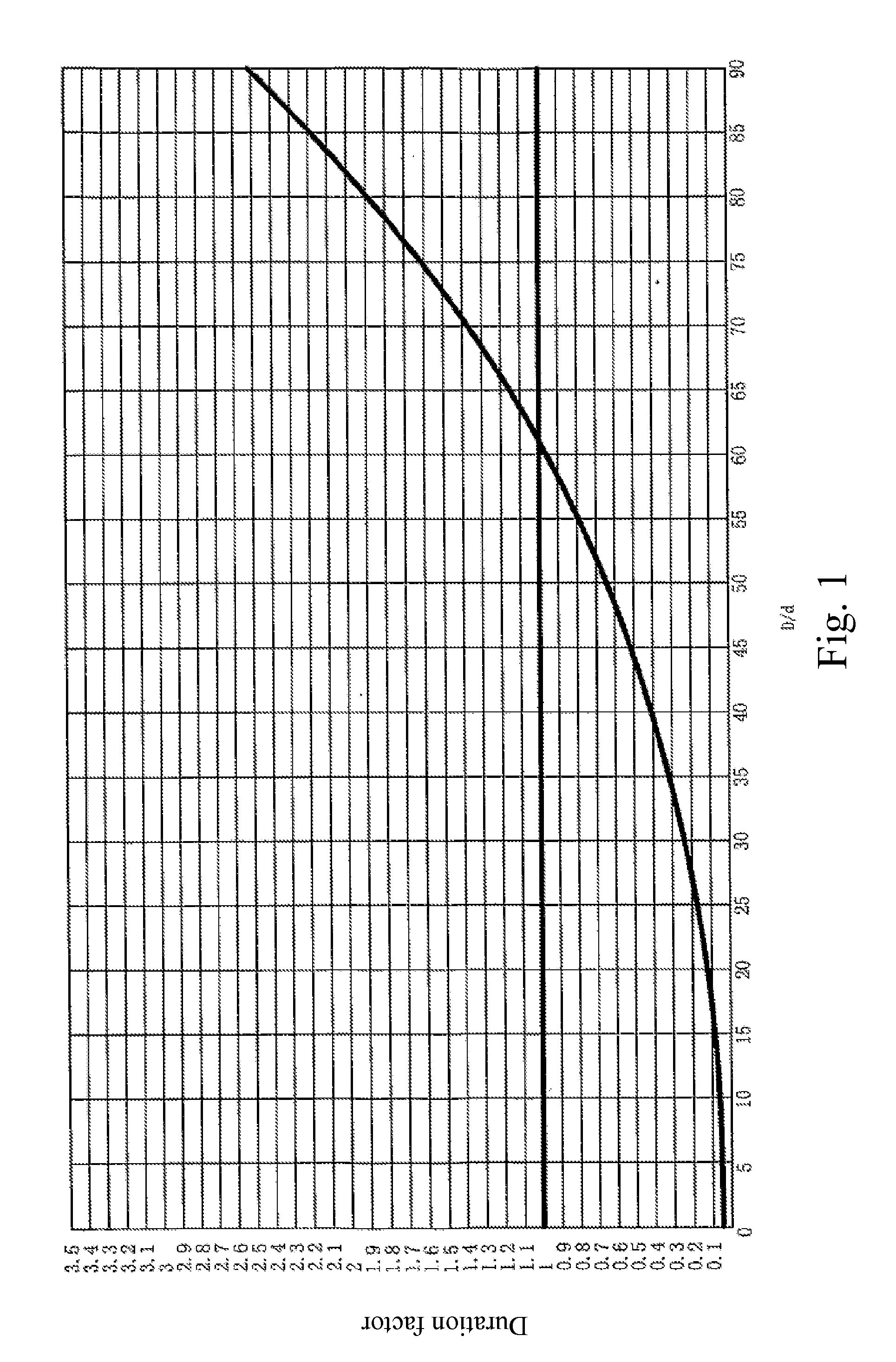
The present invention provides a tower frame combined transmitting pumping unit without guiding wheels that has a simple and safe method for giving space to drill. The unit uses a rope wheel with a large diameter to increase the distance between the tower frame and the well mouth, thereby increasing the bending diameter of the steel wires. The operation platform is a movable tower frame that can be moved away from the well mouth before drilling to move the rope wheel away from the well mouth. The thickness of the balancing weight box is reduced to save costs. The tower frame transmitting pumping unit without guiding wheels uses a platform moving device that is simple and reliable, and a transmitting system that drives the rope wheel and the weight hauling cable using a chain and gears to finish exploiting. The actuators on the platform are more compact, stable, and have a lower center of gravity. The balancing weight box has a major weight box and multiple vice weight blocks to adjust the weight to multiple levels, and is designed to match the powering system and improve efficiency. The ratio of the diameter of the rope wheel to the diameter of the steel wires is controlled between 70 and 100 to improve the duration of the steel wires.

Problems solved by technology

However, some mutually related technical problems existing in the tower frame pumping unit affects and limits wider promotion and application thereof.
The two most predominant technical problems are the method for giving space to drill and the duration of steel wires.
Because main devices of the tower frame pumping unit are provided on the top of the tower frame to form a relatively high center of gravity, it is time-consuming, energy-consuming and relatively insecure to integrally move the tower frame.
Thus a relatively small diameter of the guiding wheel leads to a relatively short duration of the steel wires.
Some conventional tower frame pumping units use belts to replace the steel wires to solve the problem of the duration of the steel wires, but the belts would shake violently under actions of winds, which tends to damage a suction rod of the pumping unit and the well mouth.
The conventional tower frame pumping units fail to simultaneously overcome the above technical problems.

Method used


Image

  • Tower frame combined transmitting pumping unit without guiding wheels
  • Tower frame combined transmitting pumping unit without guiding wheels
  • Tower frame combined transmitting pumping unit without guiding wheels

Examples


Embodiment Construction

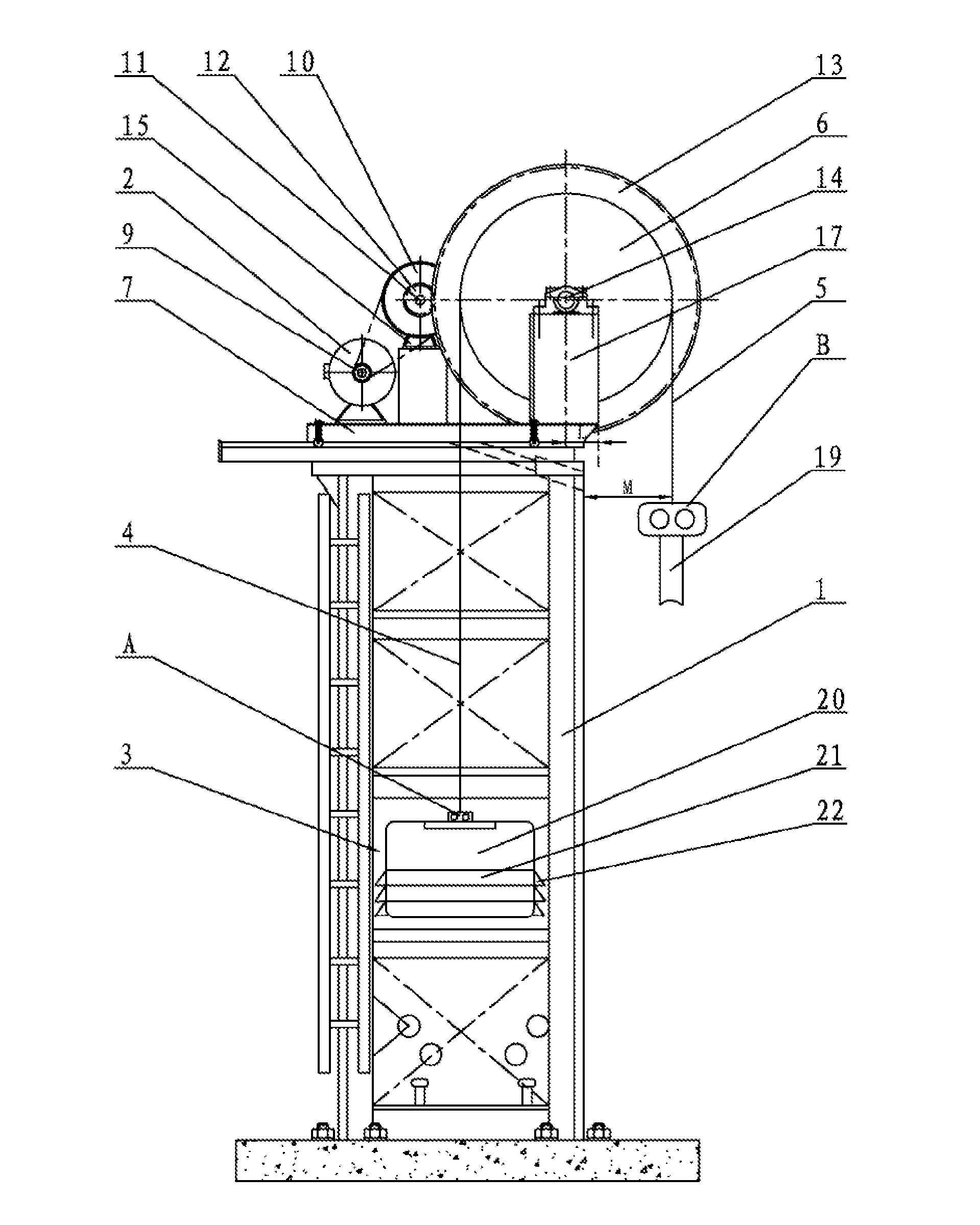
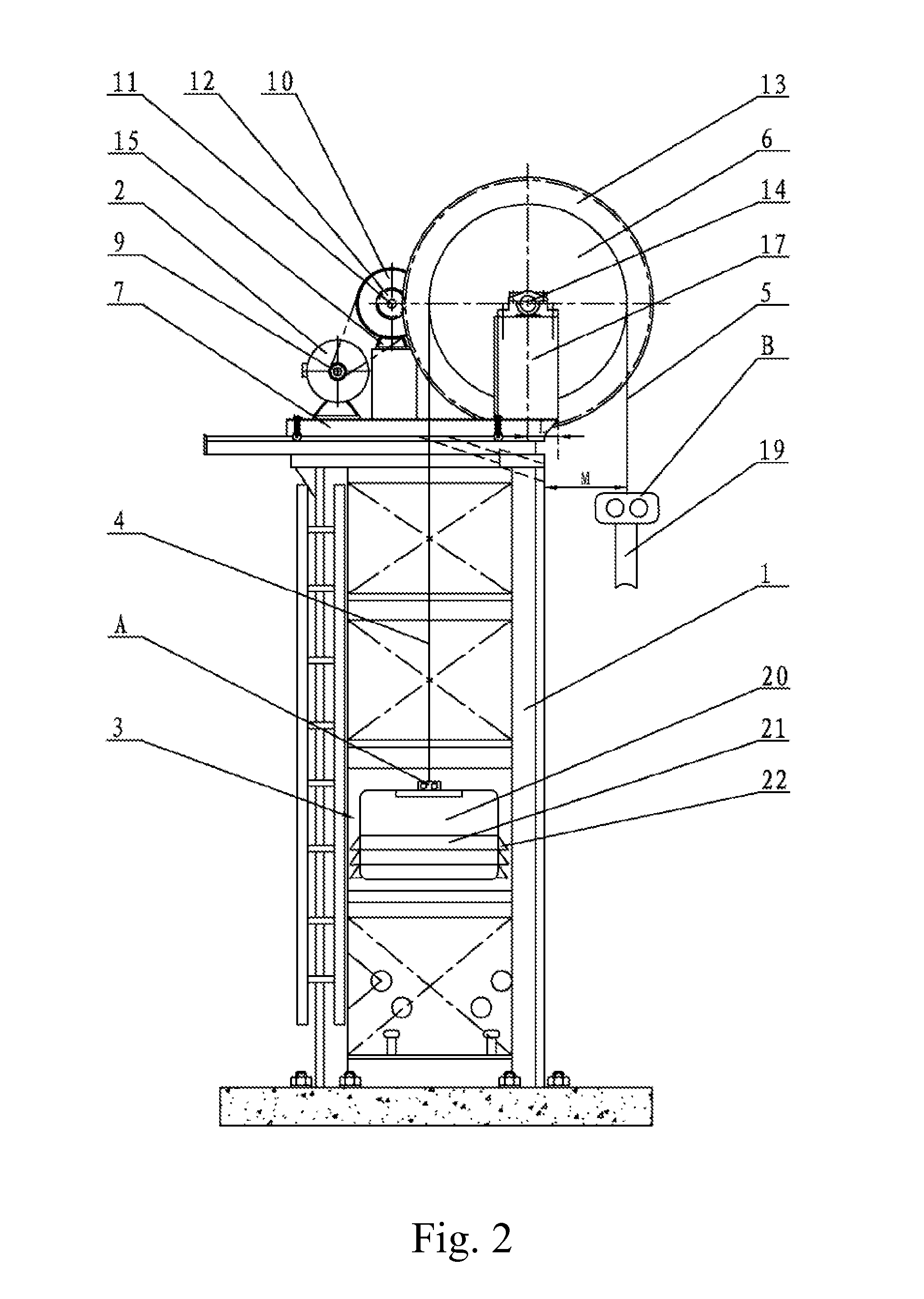
[0032]Referring to FIGS. 2 and 3 of the drawings, according to a first preferred embodiment of the present invention, a tower frame combined transmitting pumping unit without guiding wheels comprises a tower frame 1, a powering system 2, a transmitting system, a controlling system, a balancing weight box 3, a weight hauling cable 4, a driving rope 5 and rope hangers, wherein the powering system 2, the transmitting system and the rope wheel 6 are installed on an operation platform 7 at a top of the tower frame 1; the powering system 2 is a permanent magnet synchronous braking motor; the controlling system is installed in the permanent magnet synchronous braking motor; and the whole tower frame combined transmitting pumping unit without guiding wheels is controlled and operated through wireless or cable controllers by operators below the tower frame 1. Combined with FIG. 7, the transmitting system comprises a transmitting belt 8, a small belt chain wheel 9, a big belt chain wheel 10, ...


PUM


Abstract

A tower frame combined transmitting pumping unit without guiding wheels includes a tower frame, a powering system, a transmitting system, a controlling system, a balancing weight box, a weight hauling cable, a rope wheel, a driving rope and rope hangers. The rope wheel is fixed on a side of an operation platform through a rope wheel supporting device. A central axis line of the rope wheel is located within the operation platform. A wheel rim of the rope wheel extends beyond the operation platform and a minimum distance between a most external rim thereof. The weight hauling cable and the driving rope twine around the rope wheel reversely. A free end of the weight hauling cable is connected to the balancing weight box through a rope hanger A. A platform moving device is installed between the operation platform and a top of the tower frame.

Description

CROSS REFERENCE OF RELATED APPLICATION[0001]This is a U.S. National Stage under 35 USC 371 of the International Application PCT / CN2010 / 070586, filed on Feb. 9, 2010.BACKGROUND OF THE PRESENT INVENTION[0002]1. Field of Invention[0003]The present invention relates to a mechanical device for exploiting oil, and more particularly to a tower frame pumping unit.[0004]2. Description of Related Arts[0005]In the field of exploiting oil, the beam pumping unit is gradually replaced by the tower frame pumping unit because the tower frame pumping unit has a simple structure, low costs, small energy consumption and etc. However, some mutually related technical problems existing in the tower frame pumping unit affects and limits wider promotion and application thereof. The two most predominant technical problems are the method for giving space to drill and the duration of steel wires. Before drilling, in order to save enough space for the drilling devices to operate at the well mouth, a minimum di...

Claims


Application Information

Patent Timeline
IPC IPC(8): F04B9/02
CPCE21B43/126E21B15/003
Inventor MAO, HONGWEI
Owner SICHUAN MODERN CENTURY MECHANICAL & ELECTRICAL COMPANY
Learn More