
Apparatus cooperation system, image forming apparatus, and function providing method

a technology of image forming apparatus and apparatus, applied in the field of apparatus cooperation system, image forming apparatus, and function providing method, can solve the problems of not being able to determine which of the methods, and not being able to determine whether the client makes a contra

Inactive Publication Date: 2013-03-07
RICOH KK
View PDF8 Cites 8 Cited by
  • Summary
  • Abstract
  • Description
  • Claims
  • Application Information

AI Technical Summary

Benefits of technology

The present invention provides an apparatus cooperation system where multiple devices can work together to share functions. The system includes two apparatuses: the first apparatus and the second apparatus. The first apparatus has an acquisition unit, an output condition acceptance unit, an operation control unit, an output unit, a counting unit, and a data communication unit. The second apparatus has a receiving unit, an output control unit, an output unit, a counting unit, and a data communication unit. When the first apparatus sends an output request to the second apparatus, the second apparatus outputs the requested object based on its own output condition. The system can also count the number of output objects and total output objects based on pre-configured rules. The technical effects of this invention are improved cross-device cooperation, simplified user experience, and efficient data transmission.

Problems solved by technology

Further, in the counter method, the client may usually have to pay a cost for consumable supplies (e.g., toner and other parts) and a maintenance and inspection charge including the costs of exchanging parts and adjustment of the apparatus.
It is not possible to determine which of the methods is advantageous because it depends on the frequency of use of the client.
Further, it is usually unknown whether the client makes a contract based on the counter method or the toner kit method when the apparatus is shipped from the factory.

Method used


Image

  • Apparatus cooperation system, image forming apparatus, and function providing method
  • Apparatus cooperation system, image forming apparatus, and function providing method
  • Apparatus cooperation system, image forming apparatus, and function providing method

Examples


embodiment 1

[0053]FIG. 3 schematically illustrates a part of a billing system when the MFPs according to an embodiment perform a job in apparatus cooperation. The “apparatus cooperation” herein refers to a scheme in which, for example, plural apparatus cooperate with each other by sharing and providing a function necessary for (executing) a job including a series of processes from input to output.

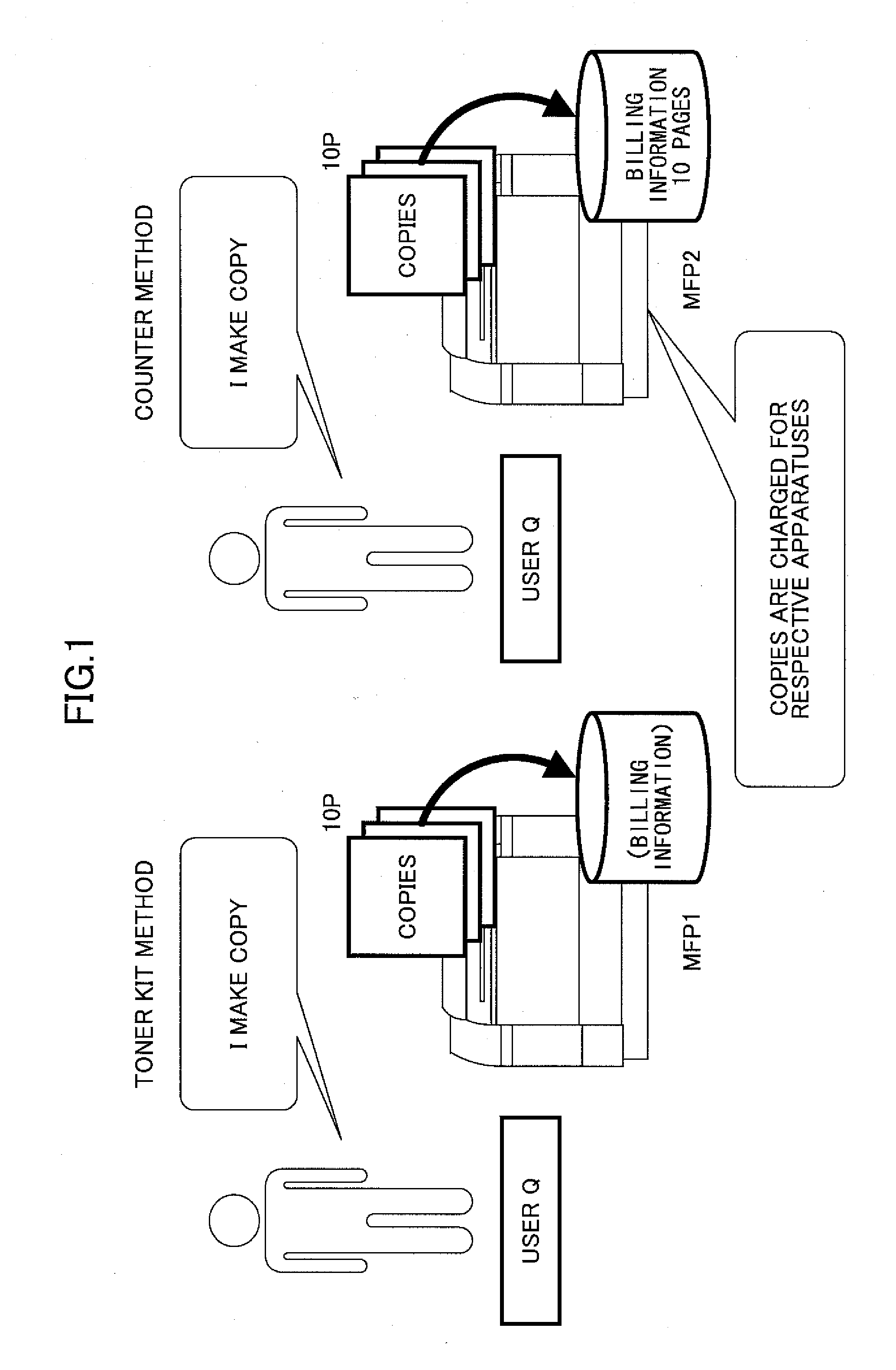
[0054]The billing system employed in the MFP (Multi Functional Peripheral) 1 and the MFP 2 (hereinafter may be referred to as “MFP 100” when not necessary to distinguish one from another) is either the toner kit method or the counter method.

[0055]In the counter method, for example, the client pays an amount corresponding to a basic charge and a charge determined by the product of the number of printed pages by contracted unit price as a monthly charge. Further, in the counter method, the client may usually have to pay a cost for consumable supplies (e.g., toner and other parts) and a maintenance and in...

example configuration

[0071]FIG. 5 illustrates an example configuration of the apparatus cooperation system 200. In the example configuration of FIG. 2, a WAN (Wide Area Network) is formed of a LAN (Local Area Network) 1 and a LAN 2. The LAN 1 is connected to the LAN 2 using an L3 switch or a router (not shown).

[0072]It should be noted that the apparatus cooperation may also be achieved even when the number of the LANs is one or more than two. In the configuration, the communications among the MFP 1 through 4, between server 1 and 2, and between MFP 1 through 4 and server 300 (hereinafter referred to as servers 1 and 2 when necessary to distinguish one from another) may be achieved by wired or wireless connections.

[0073]In LAN 1, three MFPs 1 through 3 and the server 1 are connected to each other. In LAN 2, the MFP 4 and the server 2 are connected to each other. The MFPs 1 through 4 includes at least one of a copy function, a scanner function, a FAX function, and a printing function. Further, it is not n...

embodiment 2

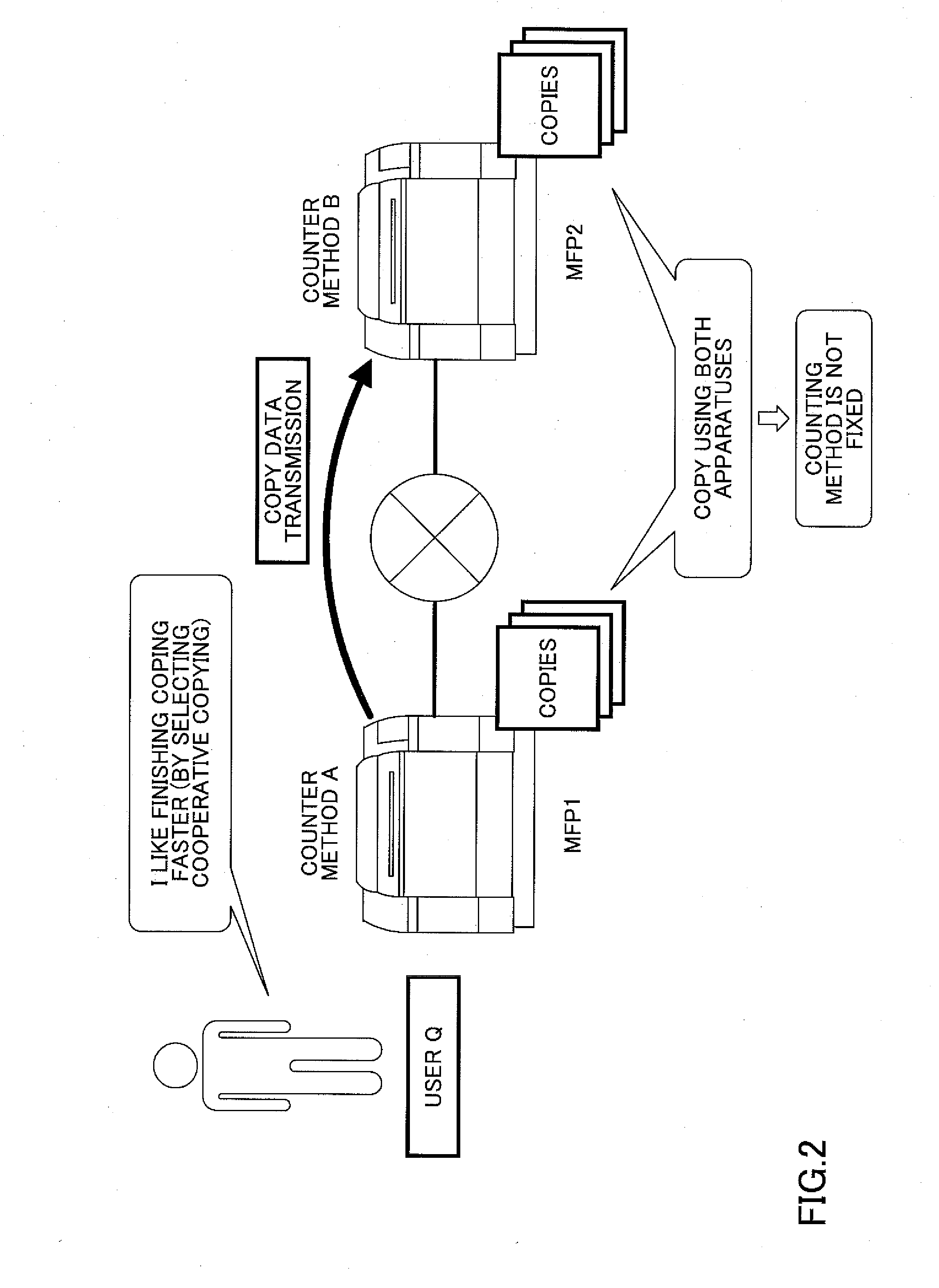
[0264]In the above Embodiment 1, the MFP 1 counts the number of pages to be charged of the MPF 2 as well. However, if the billing information items 27 of the MFP 1 differs from those of the MFP 2, the amount to be paid by the client may differ depending on whether the MFP 1 or the MFP 2 counts the number of pages to be charged. For example, if the printing cost of she MFP 2 is less expensive than that of the MFP 1, it is unbeneficial to the client.

[0265]To resolve the problem, in this embodiment, an apparatus cooperation system is described capable of preventing the apparatus cooperative job when the billing information items 27 of the MFP 1 differs from those of the MFP 2. By doing this, it becomes possible to prevent the payment unintended for the client by preventing the MFP 1 from counting all the number of pages to be charged.

[0266]FIGS. 20A and 20B are a sequence diagram illustrating an example process of executing the apparatus cooperative job by the MFP 1 and the MFP 2. In F...


PUM


Abstract

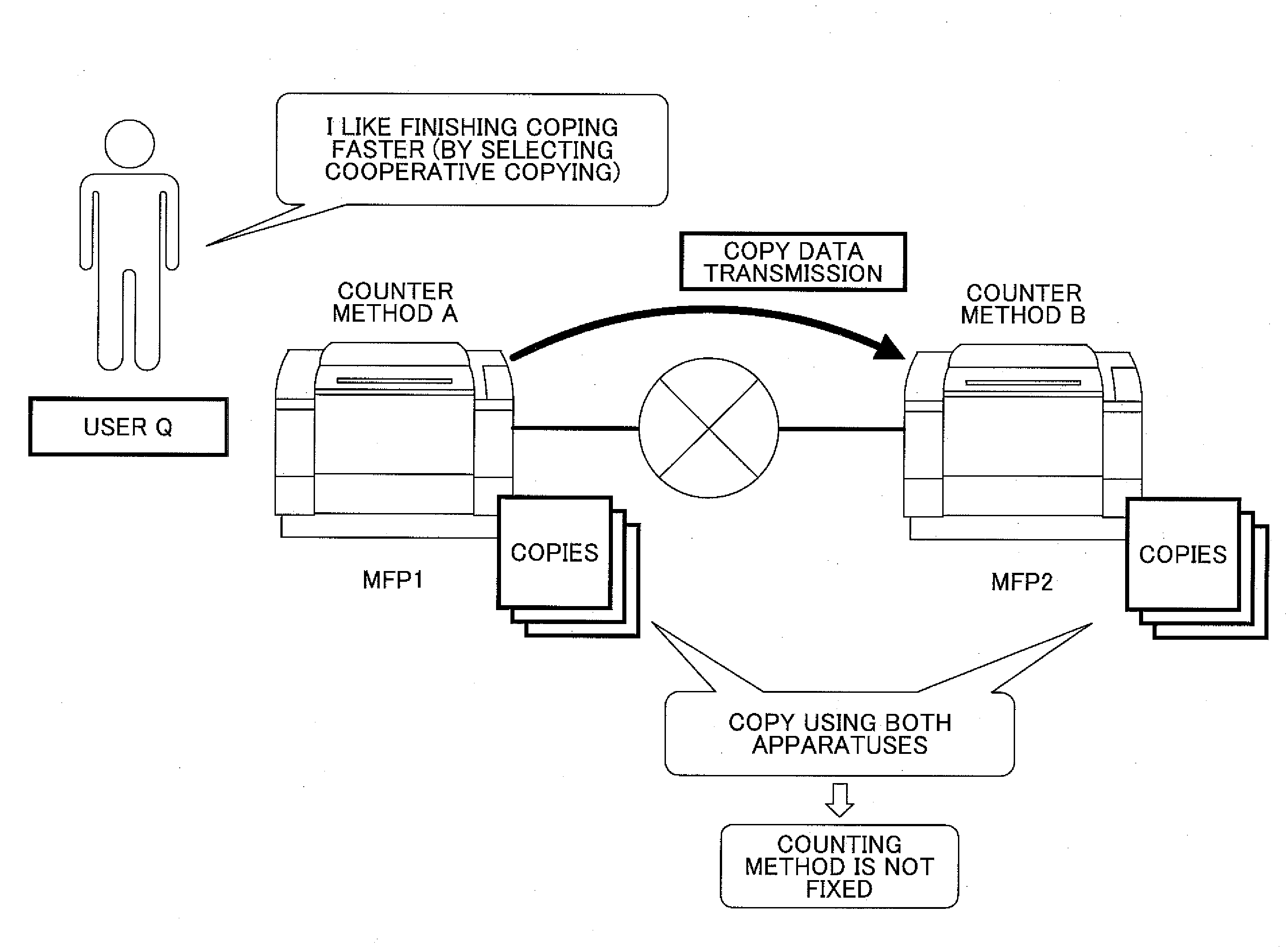
An apparatus cooperation system including first and second apparatuses connected via a network to share a function, the first apparatus including a first counting unit counting a number of the output objects output by the first output unit based on a first counting rule, the second apparatus including a second counting unit counting a number of the output objects output by the second output unit based on a second counting rule. Further, when an output condition to output the image data by the first apparatus and the second apparatus is accepted, the first counting unit counts a total number of the output objects output by the first output unit and the second output unit based on the first counting rule.

Description

CROSS-REFERENCE TO RELATED APPLICATIONS[0001]The present application claims priority under 35 U.S.C §119 to Japanese Patent Application No. 2011-194975 filed Sep. 7, 2011, the entire contents of which are hereby incorporated herein by reference.BACKGROUND OF THE INVENTION[0002]1. Field of the Invention[0003]The present invention generally relates to a apparatus cooperation system where plural apparatuses connected to each other via a network share and provide functions of the apparatuses among the apparatuses.[0004]2. Description of the Related Art[0005]The apparatuses such as copiers are generally provided to many businesses as clients on lease or rental basis. This is because those apparatuses generally require maintenance services. In this case, for example, the client pays not only a lease charge but also the other charge in accordance with the lease contract to a leasing company. To determine the other charge, there have been used a counter method and a toner kit method.[0006]I...

Claims


Application Information

Patent Timeline
Patent Type & Authority Applications(United States)
IPC IPC(8): G06F3/12
CPCG03G21/02G06F3/1205G06F3/1239Y02B60/1271G03G2215/00109G03G2215/00113G06F3/1291Y02D10/00
Inventor OHTA, SHINGO
Owner RICOH KK
Learn More