
Determining expiration time of bindings for network address translation devices

Active Publication Date: 2013-02-28
RIBBON COMM OPERATING CO INC
View PDF27 Cites 24 Cited by
  • Summary
  • Abstract
  • Description
  • Claims
  • Application Information

AI Technical Summary

Benefits of technology

The patent text describes techniques for efficiently determining the time it takes for a network device to connect to another device (known as a "binding timeout" value). By using a dynamic process, these techniques reduce network bandwidth usage and minimize connection interruptions, resulting in an efficient and effective way to learn and maintain active network bindings. This technique helps to mitigate the problem of inefficient timeout probing that leads to increased network traffic and impacts the processing throughput of servers and remote computing devices. The patent also describes a re-transmitting mechanism for re-sending of queries if no response is received, which can be performed a predetermined number of times. Overall, these techniques improve the efficiency and effectiveness of network communications.

Problems solved by technology

The paradigm of requiring a client device to initiate a flow and allowing a binding to expire if not used within a certain amount of time presents certain difficulties in the context of a SIP session.
However, the NAT binding timeout value is generally not known by the network device prior to establishing a registration because the NAT devices are not controlled by the operator of the network device.
This additional traffic substantially hampers network bandwidth and performance, and also affects the power consumption and efficiency of the client devices.
As a result, the learning method takes a long time to complete.
In this period, SIP calls initiated from the network device will not be able to reach the client device.

Method used


Image

  • Determining expiration time of bindings for network address translation devices
  • Determining expiration time of bindings for network address translation devices
  • Determining expiration time of bindings for network address translation devices

Examples


Embodiment Construction

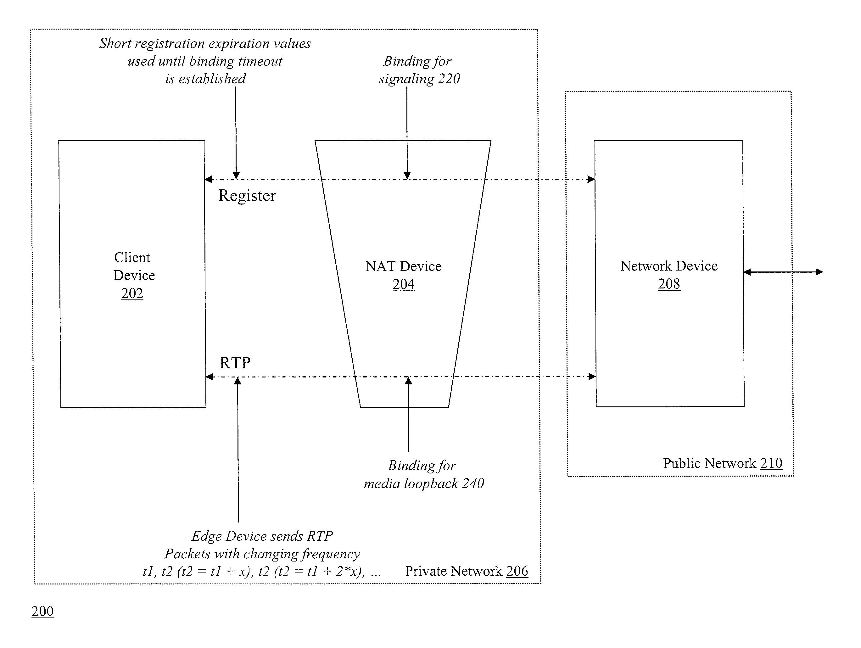
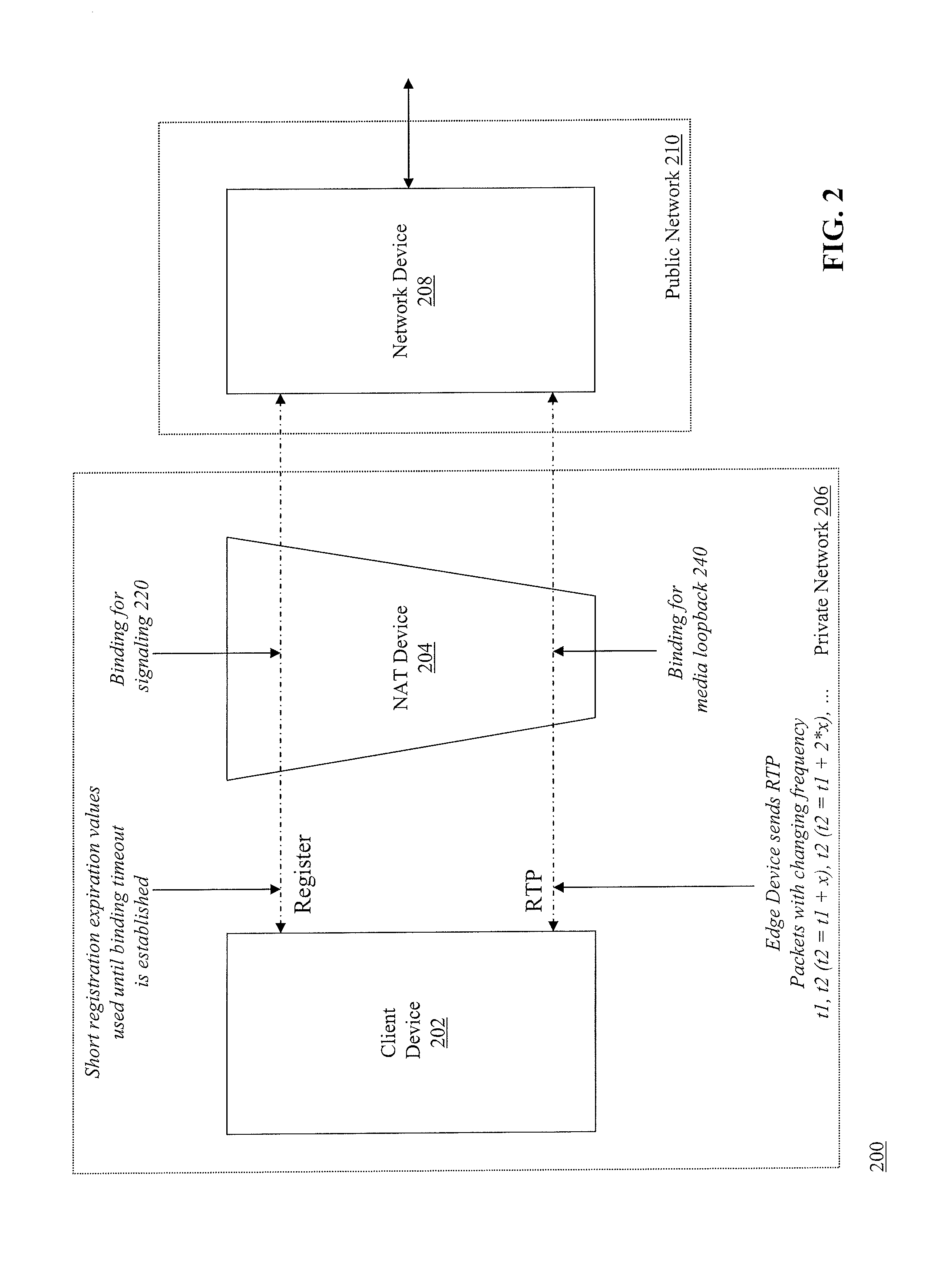
[0047]FIG. 2 is a block diagram of a system 200 for determining expiration time of bindings for NAT devices. The system 200 includes a client device 202 and a NAT device 204 located within a private network 206. The system 200 further includes a network device 208 located in a public network 210. Although FIG. 2 shows network device 208 in public network 201, it should be understood that other architectures and network configurations may be employed. For example, network device 208 can be located within private network 208. In this example, network device 208 can be an edge device, such as a session border controller (SBC), which connects to other devices (not shown) in an external public network (e.g., the Internet). One of ordinary skill in the art will understand that the techniques described herein can be implemented on many different server types, network configurations, and / or computing devices without departing from the spirit or scope of the invention.

[0048]The client device...


PUM


Abstract

Methods and apparatuses, including computer program products, are described for determining expiration time of bindings for NAT devices. A first device receives a first request including a first source IP address / port pair of a first NAT binding, and transmits a response. The first device receives a second request including a second source IP address / port pair of a second NAT binding, and transmits a response. The first device sets a refresh time T1 of the first NAT binding to be shorter than an expected minimum expiration time of the first NAT binding, transmits one or more messages via the second NAT binding where a sending interval time T2 of the second NAT binding is longer than T1, increments T2 when a response is received, and if a response to any of the messages is not received, sets T1 equal to the last T2 value for which a response was received.

Description

FIELD OF THE INVENTION[0001]The subject matter of this application relates generally to methods and apparatuses, including computer program products, for determining expiration time of bindings for network address translation (NAT) devices.BACKGROUND OF THE INVENTION[0002]The growth of Internet Protocol (IP)-based networks as carriers for various types of digital communications has led to the advent of application protocols used to negotiate and define the parameters of a communications session between two peer computing devices. One example of such an application protocol is Session Initiation Protocol (SIP), commonly used for establishing and managing Voice-over-IP (VoIP) connections.[0003]Along with the rise of IP-based networks and digital communications has come the need to protect such networks and the devices that reside on them from security vulnerabilities and attacks. To provide for secure communications, many private communication networks connect to public networks (e.g....

Claims


Application Information

Patent Timeline
IPC IPC(8): G06F15/177
CPCH04L61/2553
Inventor ASVEREN, TOLGA
Owner RIBBON COMM OPERATING CO INC
Learn More