Amperometric Sensor System

a sensor system and amperometric technology, applied in the field of amperometric sensor systems, can solve the problems of low maintenance requirements, unreliable electrode measurements, and lack of flow independent measurement methods, so as to reduce the cost of operation, reduce maintenance requirements, and stabilize quickly

Active Publication Date: 2013-02-14
HALOGEN SYST INC
View PDF5 Cites 2 Cited by
  • Summary
  • Abstract
  • Description
  • Claims
  • Application Information

AI Technical Summary

Benefits of technology

[0024]An amperometric system with low maintenance requirements is needed. The system should be able to operate for extended periods unattended. The system should operate for extended periods (e.g., for up to a year) without a sensor replacement or other maintenance. Preferably, the chlorine sensor and the pH sensor should be replaceable individually to reduce the cost of operation. Preferably, the sensor incorporates a method of overcoming the polarization effects of cyanuric acid (CYA). The sensor should not require frequent recalibration, and if a sensor is removed or replaced, a sensor should quickly stabilize and report reliable readings.
[0025]An aspect of embodiments in accordance with the present invention is a sensor system that provides a reliable sensor platform that has a long lived chlorine sensor, provides a replaceable pH sensor and requires only infrequent calibration. The sensor system provides fast measurement response times, is largely unaffected by changes in flow, pH, temperature or conductivity, and is capable of direct insertion in a pipe. The sensor is resistant to biofouling and to high levels of water hardness, which makes the sensor practical for use in the most challenging applications including seawater and wastewater as well as in cleaner applications for the measurement of chlorine in drinking water.

Problems solved by technology

A common problem encountered with online measurement of water chemistry in the field is fouled electrodes in the sensor system.
Electrode measurements can be rendered unreliable when the working electrode is covered with either inorganic (salts such as calcium carbonate) layers or organic (biofouling) layers that inhibit electrode processes.
Another problem with certain sensors is the lack of a flow independent measurement method that can installed in a process flow without adverse effects from changing flow rates on the sensor signal.
Another limitation of most sensors is the lack of an ability to directly insert a sensor into a process flow pipe or fitting for a simple installation such as may be necessary in a drinking water distribution system.
Maintenance costs of online chlorine monitors often greatly exceed the cost of the unit.
This requirement further complicates the installation, maintenance and logistical requirements.
This results in excessive water loss or unnecessary consumption.
Solution consumption and replenishment result in higher costs and maintenance requirements.
Polarization of many sensors causes a loss of sensitivity over the first 2-24 hours, requiring recalibration.
When amperometric systems with exposed electrodes are used with even low levels of cyanuric acid (CYA), a polarization of the electrode occurs with a layer of CYA that inhibits electron processes, rendering the electrode unusable after less than one day of operation due to the low signal response.
The probes used for ORP sensing often suffer from a reduction in sensitivity caused by organics, particularly when high levels of cyanuric acid are present.
Problems with these systems are well known.
Another problem with most of these systems is that they measure only hypochlorous acid, a free chlorine fraction, not free chlorine as measured by a DPD test kit.
This results in a limited operational range of 6.0 to 8.0 pH.
Beyond a pH of 8.0, the sensors produce very little signal, which can produce large errors.
In addition to these deficiencies, membrane sensors are affected by flow and pressure changes requiring recalibration when either changes.
Another issue with known sensors is the detection and / or interference of chloramines in drinking water.
Chloramines, compared to free chlorine, are both less effective as a sanitizer and more irritating to the eyes of swimmers.
When swimmers complain of eye irritation from “too much chlorine” in a pool, the problem is typically a high level of chloramines.
Some pool test kits designed for use by homeowners are sensitive to both free chlorine and chloramines, which can be misleading.
Otherwise, the sensor system may drastically under report the sanitizer levels due to the lower signal response of monochloramine.

Method used


Image

  • Amperometric Sensor System
  • Amperometric Sensor System
  • Amperometric Sensor System

Examples


Embodiment Construction

[0112]The amperometric sensor is disclosed herein with respect to exemplary embodiments. The embodiments are disclosed for illustration of the sensor system and are not limiting except as defined in the appended claims.

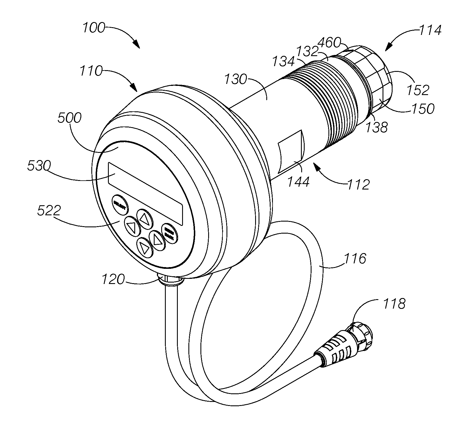
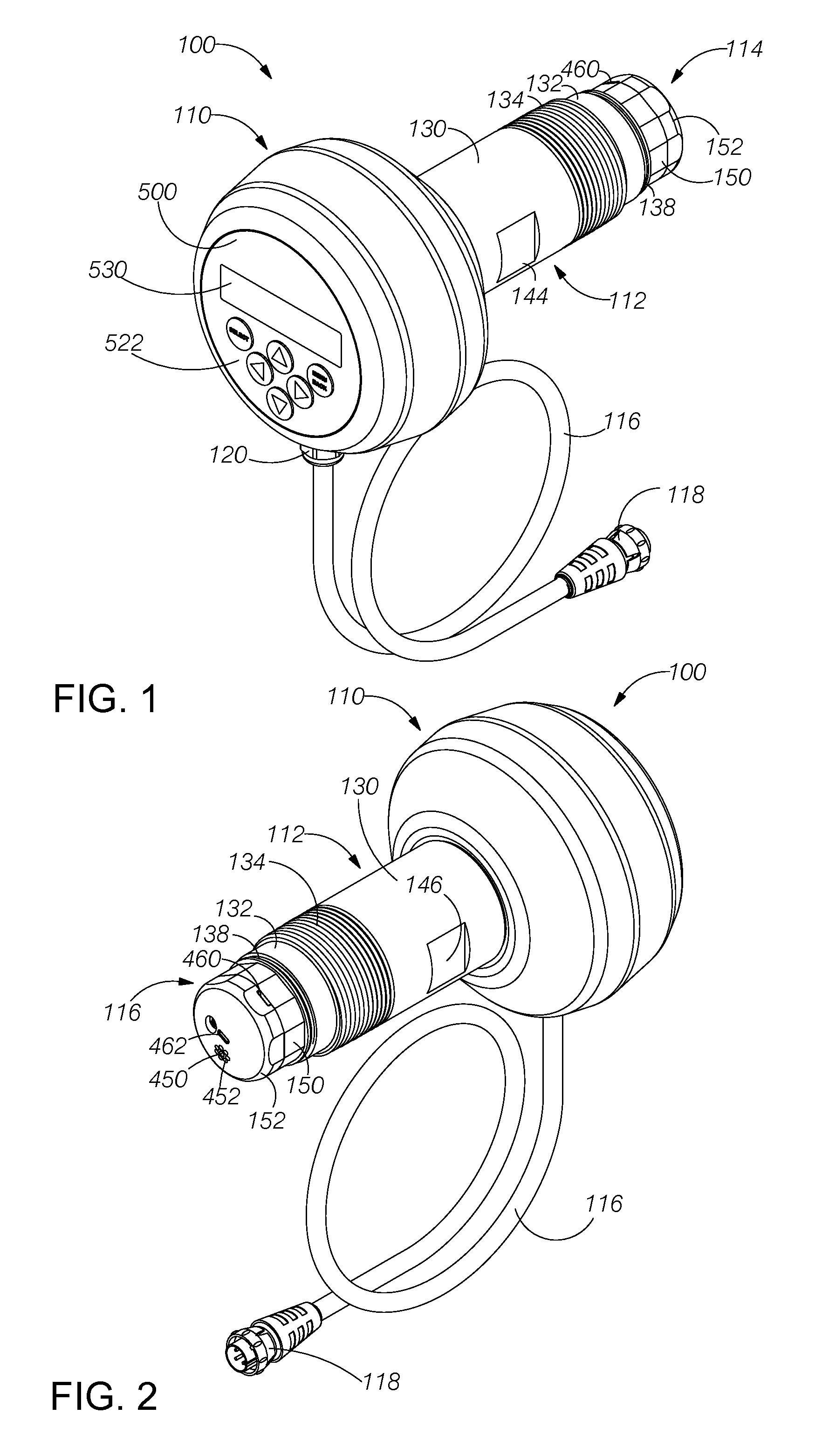
[0113]FIG. 1 illustrates a perspective view of an embodiment of a sensor system 100 in accordance with aspects of the present invention. The sensor system comprises an electronics enclosure 110, an intermediate housing 112, a sensor housing 114 and a communications cable 116. The communications cable is terminated at a free end with a connector 118. The opposite end of the communications cable enters the electronics enclosure via a liquid-tight cordgrip 120. Wires within the communications cable are terminated on a printed circuit board (not shown in FIG. 1) within the electronics enclosure as described below.

[0114]FIG. 2 illustrates a perspective view of the sensor system 100 of FIG. 1 viewed from the sensor end. FIG. 3 illustrates a right side elevational view of th...


PUM

PropertyMeasurementUnit
voltageaaaaaaaaaa
voltageaaaaaaaaaa
voltageaaaaaaaaaa

Abstract

A sensor system that measures at least one parameter of water includes an electronics subsystem and includes a sensor housing electrically and mechanically coupled to the electronics subsystem. The sensor housing encloses a chamber that receives water via at least one inlet and that releases water via at least one outlet. At least one sensor has at least one electrode exposed to water in the chamber. A flow generator causes water to flow through the chamber. A plurality of objects within the chamber move in response to the water flow and abrasively clean the at least one electrode. Preferably, the sensor system includes a chlorine sensor having at least two electrodes. The electronics subsystem applies a first differential voltage between the two electrodes during a measurement interval and then applies a second differential voltage between the two electrodes during an interval following the measurement interval.

Description

RELATED APPLICATIONS[0001]The present application is a divisional application of U.S. patent application Ser. No. 13 / 372,260 filed on Feb. 13, 2012, which claims the benefit of priority under 35 USC §119(e) to U.S. Provisional Application No. 61 / 443,240, filed on Feb. 15, 2011, to U.S. Provisional Application No. 61 / 548,953, filed on Oct. 19, 2011, to U.S. Provisional Application No. 61 / 597,762, filed on Feb. 11, 2012, and to U.S. Provisional Application No. 61 / 597,832, filed on Feb. 12, 2012, which are incorporated by reference herein.BACKGROUND OF THE INVENTION[0002]1. Field of the Invention[0003]The present invention is in the field of systems for testing water chemistry, and, more particularly, is in the field of amperometric sensors.[0004]2. Description of the Related Art[0005]Amperometric chlorine sensors are used in measuring chlorine residuals in drinking water, wastewater, cooling towers. Some newer applications are measurement of Total Residual Oxidant (TRO) in seawater. R...

Claims


Application Information

Patent Timeline
Patent Type & Authority Applications(United States)
IPC IPC(8): G01N33/18G01N27/00H05K13/00
CPCG01N27/4168Y10T29/49002G01N27/06G01N27/08G01N33/18G01N33/1893G01N27/26F04D1/04
Inventor SILVERI, MICHAEL A.
Owner HALOGEN SYST INC
Why Eureka
Try Eureka