
Catadioptric system and image pickup apparatus

a catadioptric system and image pickup technology, applied in the field of catadioptric system and image pickup apparatus, can solve the problems of not necessarily providing an observation field of view having a sufficient size, not necessarily providing an image data acquisition through image capture, and requiring a long time. , to achieve the effect of good image side telecentricity, wide wavelength range, and high optical performan

Active Publication Date: 2013-02-07
CANON KK
View PDF3 Cites 4 Cited by
  • Summary
  • Abstract
  • Description
  • Claims
  • Application Information

AI Technical Summary

Benefits of technology

The invention is a special optical system that uses a special surface to capture images. It has good image quality across a wide range of wavelengths and is useful for observation in a wide field of view. Overall, this system produces high-quality images and is a good choice for a variety of applications.

Problems solved by technology

However, the use of the virtual microscope has a problem that acquisition of the image data of the pathology specimen through image capturing requires a long time.
The microscope objective lens disclosed in Japanese Published Examined Patent Application No. 60-034737 sufficiently reduces various aberrations over the entire visible wavelength range, but does not necessarily provide an observation field of view having a sufficient size.
Also, the wideband microscope catadioptric imaging system disclosed in Japanese Patent Laid-Open No. 2007-514179 sufficiently reduces aberrations over a wide wavelength range and has high resolving power, but does not necessarily provide an observation field of view having a sufficient size.
Furthermore, the catadioptric imaging system disclosed in WIPO Patent Application WO00 / 039623 has high resolving power over a wide wavelength range, but does not necessarily corrects aberrations in a sufficiently wide wavelength range.
However, if the objective lens in the microscope system has low telecentricity on its image side, displacement of positions of the image sensors in a direction of an optical axis due to manufacturing errors or focus adjustment generates distortion.
In such a case, number of pixels to be used only as the overlapping portions for joining of the image data is increased with respect to the wide-screen image data to be acquired, which increases volume of data and thereby makes it difficult to acquire the wide-screen image data at high speed.
However, even if simply using such an aspheric optical surface, it is difficult to correct various aberrations well over a wide wavelength range and to achieve high optical performance over a wide observation field of view.

Method used


Image

  • Catadioptric system and image pickup apparatus
  • Catadioptric system and image pickup apparatus
  • Catadioptric system and image pickup apparatus

Examples


embodiment 1

[0076]In the following description, a specimen (object) side surface of each lens is referred to “as an R1 surface”, and an image sensor (image) side surface of each lens is referred to as “an R2 surface”.

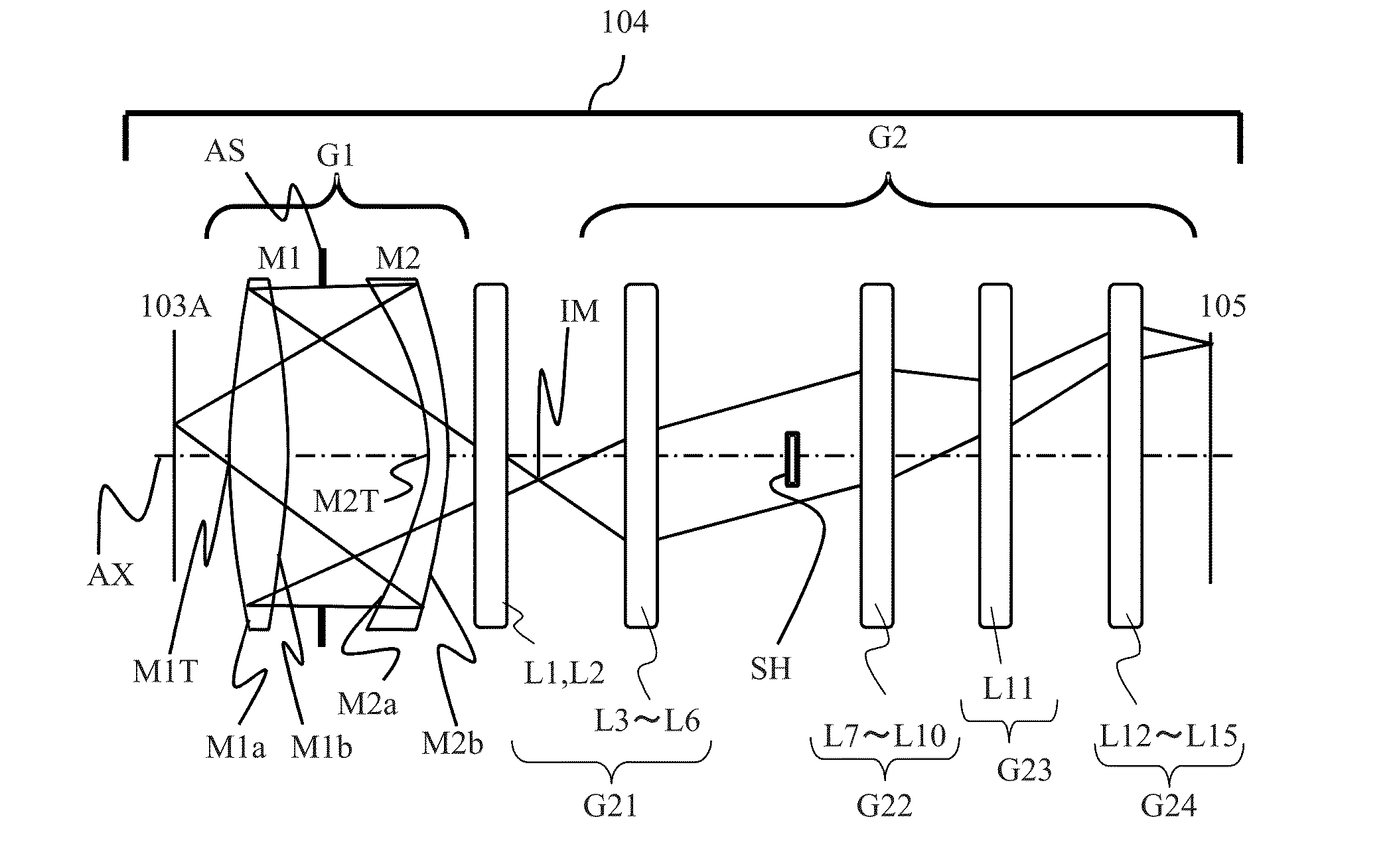
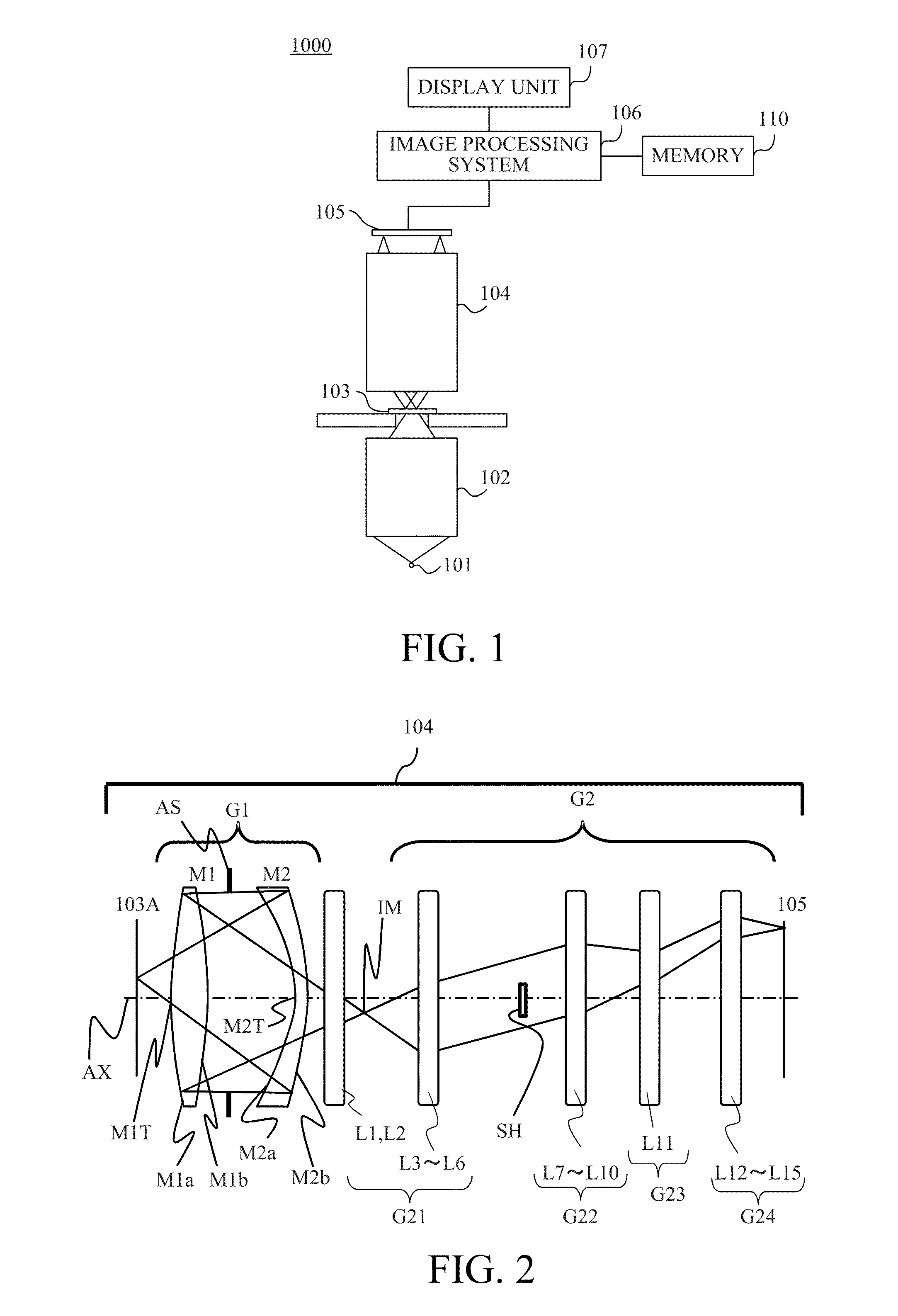
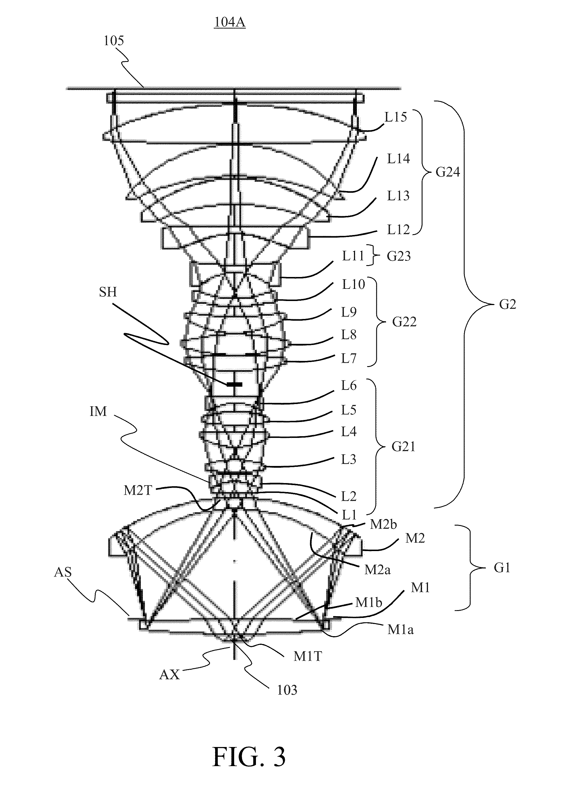
[0077]In Embodiment 1, the R2 surface of the lens L7 in the second lens group G22 is the aspheric surface including the inflexion point. The R2 surface of the lens L7 has a negative optical power on and around the optical axis AX and has a positive refractive power in its peripheral portion, which provides good telecentricity not on the object side, but also on the image side. The ratio of the distance D of the outermost off-axis principal ray from the optical axis AX on the R2 surface of the lens L7 to the maximum image height Ymax is as follows:

D / Ymax=0.094.

[0078]Embodiment 1 thus employs the aspheric surface having the inflexion point as a lens surface on which light fluxes of respective image heights impinge at mutually different positions, thereby enabling provision of good te...

embodiment 2

[0082]In Embodiment 2, the R2 surface of the lens L7 in the second lens group G22 and the R1 surface of the lens L15 in the fourth lens group G24 are the aspheric surfaces each including the inflexion point. Embodiment 2 is different from Embodiment 1 in that two aspheric surfaces each including the inflection point are included. Each of the R2 surface of the lens L7 and the R1 surface of the lens L15 has a negative optical power on and around the optical axis AX and has a positive refractive power in its peripheral portion, which provides good telecentricity not on the object side, but also on the image side.

[0083]The ratio of the distance D (D1) of the outermost off-axis principal ray from the optical axis AX on the R2 surface of the lens L7 to the maximum image height Ymax is as follows:

D1 / Ymax=0.091.

[0084]And, the ratio of the distance D (D2) of the outermost off-axis principal ray from the optical axis AX on the R1 surface of the lens L15 to the maximum image height Ymax is as ...

numerical examples 1

[0093]

25th surface D / Ymax = 0.094SurfaceNo.rdNdνdOBJ5.00 1571.789.371.5264.1 2−3609.2572.99 3−85.687.361.5264.1 4−116.17−7.361.5264.1 5−85.68−72.99 6 (AS)1E+180.00 7−3609.25−9.371.5264.1 8571.789.371.5264.1 9−3609.2572.9910−85.687.361.5264.111−116.173.0012−1000.007.731.6263.313−23.795.001.7432.314−69.260.851580.298.751.6263.316−46.848.351734.989.471.4970.218267.475.1219102.438.851.7535.320−57.485.4721−28.655.001.6236.322−1302.773.2223 (SH)1E+1813.062494.229.741.4970.225872.060.892692.0213.971.7647.827−73.690.502850.2310.911.5961.129150.526.603067.985.261.7627.53148.2317.2332−28.975.001.7444.833384.1020.7234−39.105.001.5264.135−1000.0014.3436−109.2917.241.7444.837−66.981.4938−124.3920.681.7640.139−77.760.50401280.4325.871.6558.641−245.911.50421E+186.001.5264.1431E+183.00IP0.00(Aspheric Coefficients)SurfacekABCDNo.EFGHJ1, 8 0.00E+002.17E−08−7.88E−132.62E−165.08E−20−2.24E−234.77E−27−3.83E−310.00E+000.00E+004, 110.00E+001.56E−081.48E−121.13E−164.86E−211.53E−24−1.25E−281.61E−320.00E+000....


PUM


Abstract

The catadioptric system includes a first imaging optical system collecting light from an object and a second imaging optical system causing the light from the first imaging optical system to form an intermediate image and to cause the light from the intermediate image to form an optical image. The first imaging optical system includes a first optical element including a first light transmissive portion and a first back reflective portion, and a second optical element including a second light transmissive portion and a second back reflective portion. The first light transmissive portion, the second back reflective portion, the first back reflective portion and the second light transmissive portion introduce the light from the object to the second imaging optical system. The second imaging optical system includes an aspheric lens having a negative refractive power on and around the optical axis and a positive refractive index in its peripheral portion.

Description

BACKGROUND OF THE INVENTION[0001]1. Field of the Invention[0002]The present invention relates to a catadioptric system suitable for observing an enlarged optical image of an object, and to an image pickup apparatus including the catadioptric system.[0003]2. Description of the Related Art[0004]Conventional pathology inspections use an optical microscope through which a pathology specimen (sample) is observed directly by person's eyes. On the other hand, recent pathology inspections use a virtual microscope capturing image data of the pathology specimen to allow observation of the image data displayed on a monitor. Such a virtual microscope enables plural persons to simultaneously observe the image data of the pathology specimen displayed on the monitor. Moreover, the use of the virtual microscope provides many advantages such as asking a distant pathologist for diagnosis using shared image data. However, the use of the virtual microscope has a problem that acquisition of the image da...

Claims


Application Information

Patent Timeline
IPC IPC(8): G02B13/16G02B17/08
CPCG02B21/04G02B17/0808
Inventor KATASHIBA, YUJI
Owner CANON KK
Learn More