Nuclear Magnetic Resonance Spectrometer and Method of Magnetic Field Correction

a technology of nuclear magnetic resonance and magnetic field correction, which is applied in the direction of magnetic measurements, liquid/fluent solid measurements, instruments, etc., can solve the problems of time-consuming methods, inability to obtain information indicating what position within the sample is shifted by what frequency, and inability to forecast the electrical energized position of the shim coil, etc., to achieve efficient correction

Active Publication Date: 2013-01-31
JEOL LTD
View PDF5 Cites 6 Cited by
  • Summary
  • Abstract
  • Description
  • Claims
  • Application Information

AI Technical Summary

Benefits of technology

[0035]The NMR spectrometer constructed in this way can efficiently correct the static magnetic field applied to the sample that is spun about an axis tilted at the magic angle with respect to the static magnetic field.
[0080]According to this NMR spectrometer, the static magnetic field applied to the sample that is spun about the axis tilted at the first angle with respect to the static magnetic field can be efficiently corrected.

Problems solved by technology

That is, in this method, it is impossible to obtain information indicating what position within the sample is shifted by what frequency (i.e., the static magnetic field is shifted).
Therefore, it is impossible to forecast what shim coil should be electrically energized in order to improve the homogeneity of the static magnetic field.
In this method, however, plural NMR measurements are needed and so this method is time-consuming.
Furthermore, there is another problem that different results arise when an operator having different skills manipulates the instrument.
Therefore, efficient magnetic field correction cannot be achieved with shim terms expanded around the Z-axis.
In this way, where NMR measurements are performed while spinning the sample about an axis tilted from the direction of the static magnetic field (Z-axis direction), the static magnetic field cannot be efficiently corrected in some cases.
Hence, it is time-consuming to make measurements.
Furthermore, there is the problem that the instrument is complicated because a three-dimensional gradient magnetic field pulse system is required.

Method used


Image

  • Nuclear Magnetic Resonance Spectrometer and Method of Magnetic Field Correction
  • Nuclear Magnetic Resonance Spectrometer and Method of Magnetic Field Correction
  • Nuclear Magnetic Resonance Spectrometer and Method of Magnetic Field Correction

Examples


first modified embodiment

[0159](1) A first modified embodiment is first described.

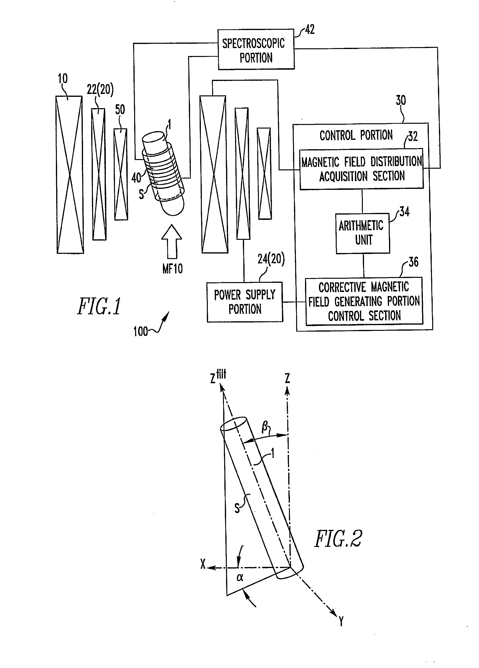
[0160]In the above-described example of nuclear magnetic resonance spectrometer 100, the angle β (made between the Z-axis and the Ztilt-axis) shown in FIG. 2 is the magic angle θm. The angle β may also be π / 2. That is, in this modified embodiment, the sample S in the sample tube 1 is spun about an axis tilted at or substantially at the angle of π / 2 with respect to the static magnetic field and the resulting NMR signal is measured. For example, the axis tilted substantially at the angle π / 2 with respect to the static magnetic field is an axis tilted at an angle in the range (π / 2)−5°≦β≦(π / 2)+5°.

[0161]In Eq. (5) above, with respect to the first-order magnetic field component BZ(1)tilt of the corrective magnetic field along the Ztilt-axis, the coefficients of BZ(1) and BZ(3) are null when β=π / 2. Therefore, BZ(1) does not affect the magnetic field component BZ(1)tilt. Also, BZ(3) does not affect the magnetic field component BZ(3)ti...

second modified embodiment

[0167](2) A second modified embodiment is next described.

[0168]In the above-described example of nuclear magnetic resonance spectrometer 100, the angle β (angle made between the Z-axis and the Ztilt-axis) shown in FIG. 2 is the magic angle θm. In contrast, in this modified embodiment, the angle β should satisfy the relationship, 5 cos2 β−3=0. That is, the angle β can be approximately 39°. The angle satisfying the relationship, 5 cos2 β−3=0, is herein referred to as the first angle θ1. In this modified embodiment, the sample S in the sample tube 1 is spun about an axis tilted strictly at the first angle θ1(β=θ1) with respect to the static magnetic field and the resulting NMR signal is measured. In addition, the sample S can be spun about an axis tilted substantially at the first angle θ1 with respect to the static magnetic field. That is, the axis is tilted at an angle, for example, lying in the range θ1−5≦β≦θ1+5°.

[0169]In Eq. (5), when β=θ1, all of the first-order and second-order m...

third modified embodiment

[0175](3) A third modified embodiment is next described.

[0176]Where there are plural NMR signals, it is impossible to create a magnetic field map using a spin echo method or a gradient echo method. As such, a magnetic field map can be created, even if there are plural signals, by exciting only certain peaks instead of excitation of the first 90-degree pulse used in a spin echo method or gradient echo method.


PUM


Abstract

In a nuclear magnetic resonance (NMR) spectrometer, a sample spins about an axis tilted at a magic angle, a corrective magnetic field generating portion produces a corrective magnetic field, and a control portion controls the operation of the corrective magnetic field generating portion. An arithmetic unit included in the control portion uses at least one of BZ(1), B1(1)e, and B1(1)o or the linear sum of at least two of them as the first-order magnetic field component of the corrective magnetic field, uses at least one of B2(2)e, B2(2)o, B2(1)e, and B2(1)o or the linear sum of at least two of them as the second-order magnetic field component of the corrective magnetic field, and uses at least one of BZ(3), B3(1)e, B3(1)o, B3(2)e, B3(2)o, B3(3)e, and B3(3)o or the linear sum of at least two of them as the third-order magnetic field component of the corrective magnetic field.

Description

BACKGROUND OF THE INVENTION[0001]1. Field of the Invention[0002]The present invention relates to a nuclear magnetic resonance spectrometer and also to a method of magnetic field correction.[0003]2. Description of Related Art[0004]In NMR (nuclear magnetic resonance) spectroscopy, the resonance frequency ω is in proportion to the strength B0 of the static magnetic field and to the gyromagnetic ratio γ of nuclear spins, as given byωideal=γB0 [0005]Therefore, the positions of peaks appearing in an NMR spectrum directly reflect the strength of the static magnetic field. As a result, the distribution (lineshape) of peak positions reflects the distribution of the static magnetic field. Accordingly, in high-resolution NMR spectroscopy, there is an intrinsic requirement for high static field homogeneity. Where static magnetic field strengths are distributed spatially, if the difference with an ideal static magnetic field strength is given by δB(r), then the distribution of resonant frequenci...

Claims


Application Information

Patent Timeline
Patent Type & Authority Applications(United States)
IPC IPC(8): G06F19/00
CPCG01R33/307G01R33/243
Inventor NISHIYAMA, YUSUKE
Owner JEOL LTD
Why Eureka
Try Eureka