Processsing unit and micro controller unit (MCU)

Active Publication Date: 2013-01-24
SANKEN ELECTRIC CO LTD
View PDF11 Cites 7 Cited by
  • Summary
  • Abstract
  • Description
  • Claims
  • Application Information

AI Technical Summary

Benefits of technology

The present invention aims to reduce the loads on both system processing and filter operation, improve power consumption and performance. This is achieved by providing a technology that can improve the performance of the CPU used in the system and shorten the sampling period for digital control of power supply. This reduces the size and cost of the power supply unit and filter circuit.

Problems solved by technology

This results in the increase of power consumption in itself and the reduction in power efficiency of the power supply during low load conditions.
On the other hand, under a circumstance in which a performance of the CPU used in the system is low or does not satisfy required data processing, it causes a problem that a sampling period for digital control becomes longer, and accordingly the cycle of a pulse width modulation (PWM) waveform which drives the power MOS transistor of a converter circuit in power supply system does not become short.
As a result, the constant of an LC filter circuit on an external power circuit becomes larger, and the size of a power supply unit and the cost thereof are both increased.

Method used


Image

  • Processsing unit and micro controller unit (MCU)
  • Processsing unit and micro controller unit (MCU)
  • Processsing unit and micro controller unit (MCU)

Examples


embodiment

Effect of Embodiment

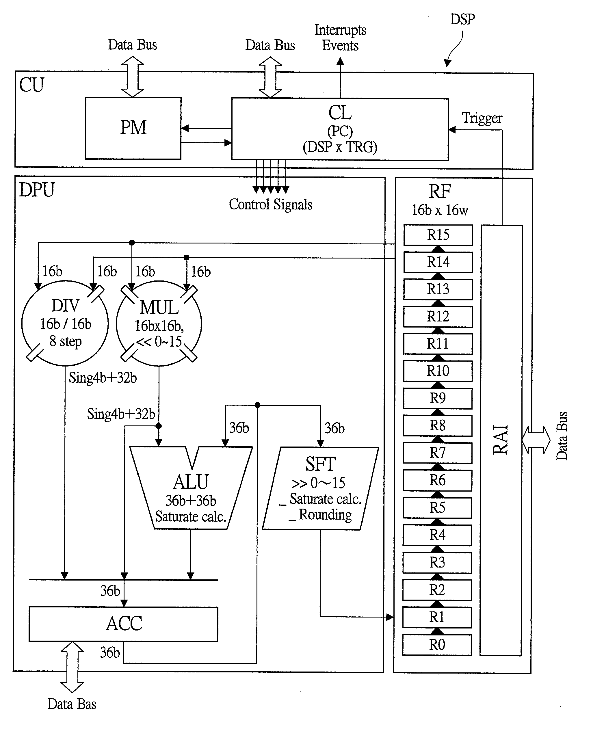
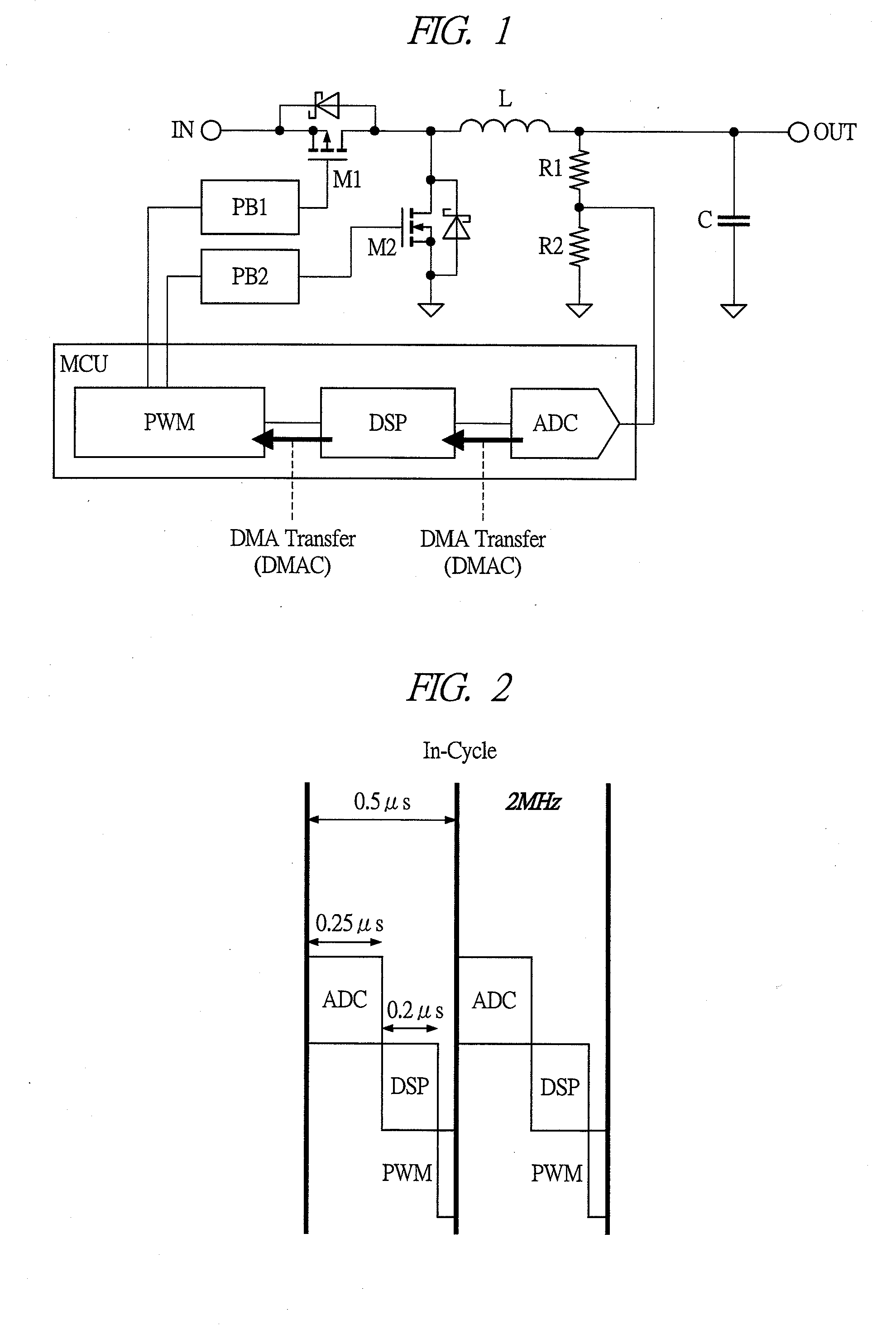
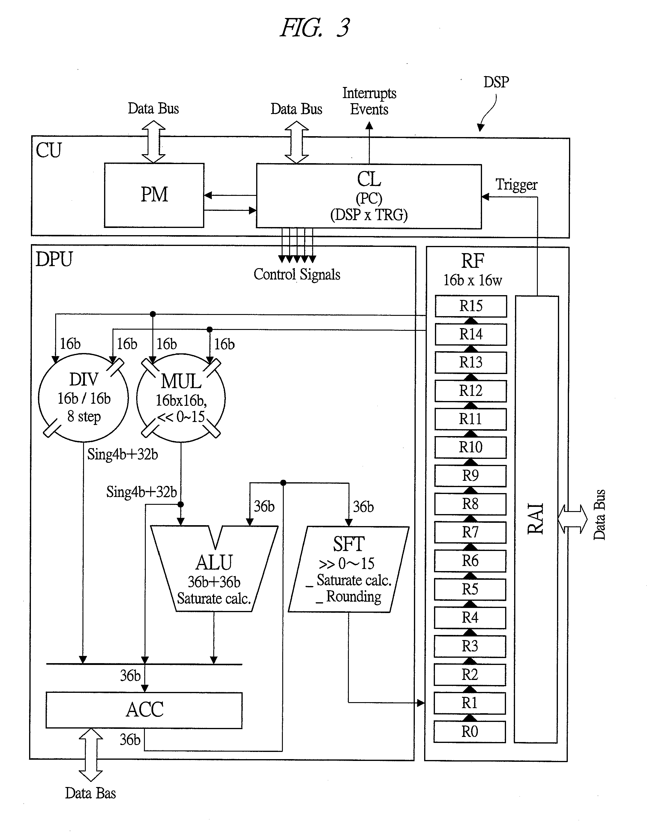
[0128]According to the embodiment described above, a program memory PM, a program counter PC, a control logic circuit CL, a plurality of registers Rn and others are provided in the digital signal processor DSP, and an A / D converter ADC, a digital signal processor DSP, a pulse width modulator PWM, a direct memory access controller DMAC, a central processing unit CPU and others are provided in the micro controller unit MCU having the DSP built therein. As a result, the following effects can be achieved.

[0129](1) Since the TRIG_WAIT flag and the TRIG_WHAT field are provided in the bit field of each instruction, the control logic circuit CL can carry out the control in such a manner that the instruction whose TRIG_WAIT flag is cleared is executed as is to proceed to the next instruction processing. Moreover, the control logic circuit CL can carry out the control in such a manner that execution of an instruction whose TRIG_WAIT flag is set is stopped if the execution ...

modification example of embodiment

[0135]In the embodiment described above, the writing to the data register of the digital signal processor DSP is used as an instruction restarting condition, but an example that uses the reading from the data register of the DSP as an instruction restarting condition is also possible. In this case, even if the data register of the DSP in which the operation result is stored is not read out, the result value is prevented from being overwritten and deleted.

[0136]In the foregoing, the invention made by the inventor of the present invention has been concretely described based on the embodiments. However, it is needless to say that the present invention is not limited to the foregoing embodiments and various modifications and alterations can be made within the scope of the present invention.

[0137]The processing unit of the present invention can be effectively applied particularly to a processing unit such as a digital signal processor built in a micro controller unit for a digital contro...


PUM


Abstract

A technology capable of reducing load on both system processing and filter operation and improving power consumption and performance is provided. In a digital signal processor, a program memory, a program counter, and a control logic circuit are provided, and a bit field of each instruction includes instruction stop flag information and bit field information. Also, the control logic circuit carries out the control in such a manner that the instruction whose instruction stop flag information is cleared is executed as is to proceed to the next instruction processing, execution of the instruction whose instruction stop flag information is set is stopped if an execution resumption trigger condition corresponding to the bit field information is not satisfied, and the instruction whose instruction stop flag information is set is executed if the execution resumption trigger condition corresponding to bit field information is satisfied, to proceed to the next instruction processing.

Description

CROSS-REFERENCE TO RELATED APPLICATION[0001]The present application claims priority from Japanese Patent Application No. 2011-160290 filed on Jul. 21, 2011, the content of which is hereby incorporated by reference into this application.TECHNICAL FIELD OF THE INVENTION[0002]The present invention relates to a technology of a processing unit, and more particularly to a technology effectively applied to a processing unit such as a digital signal processor (DSP) built in a micro controller unit (MCU) for a digital controlled power supply system and a micro controller unit having the processing unit built therein.BACKGROUND OF THE INVENTION[0003]For example, in a micro controller for use with a digital controlled power supply system, the digital controlled power supply system needs a digital filter operation function for the calculation for phase compensation in its feedback control loop. In order to enable such digital filter operation function in addition to other various operation func...

Claims


Application Information

Patent Timeline
IPC IPC(8): G06F9/30
CPCG06F9/30079G06F9/30072G06F9/30032G06F9/3001
Inventor YAMAZAKI, TAKANAGA
Owner SANKEN ELECTRIC CO LTD
Why Eureka
Try Eureka