Implantable nerve wrap for nerve stimulation configured for far field radiative powering
- Summary
- Abstract
- Description
- Claims
- Application Information
AI Technical Summary
Benefits of technology
Problems solved by technology
Method used
Image
Examples
second embodiment
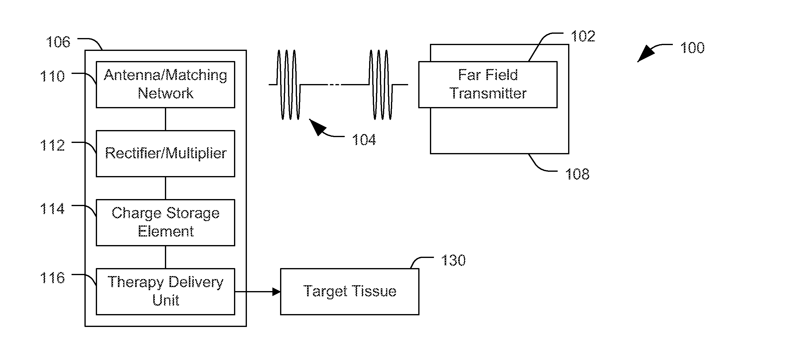
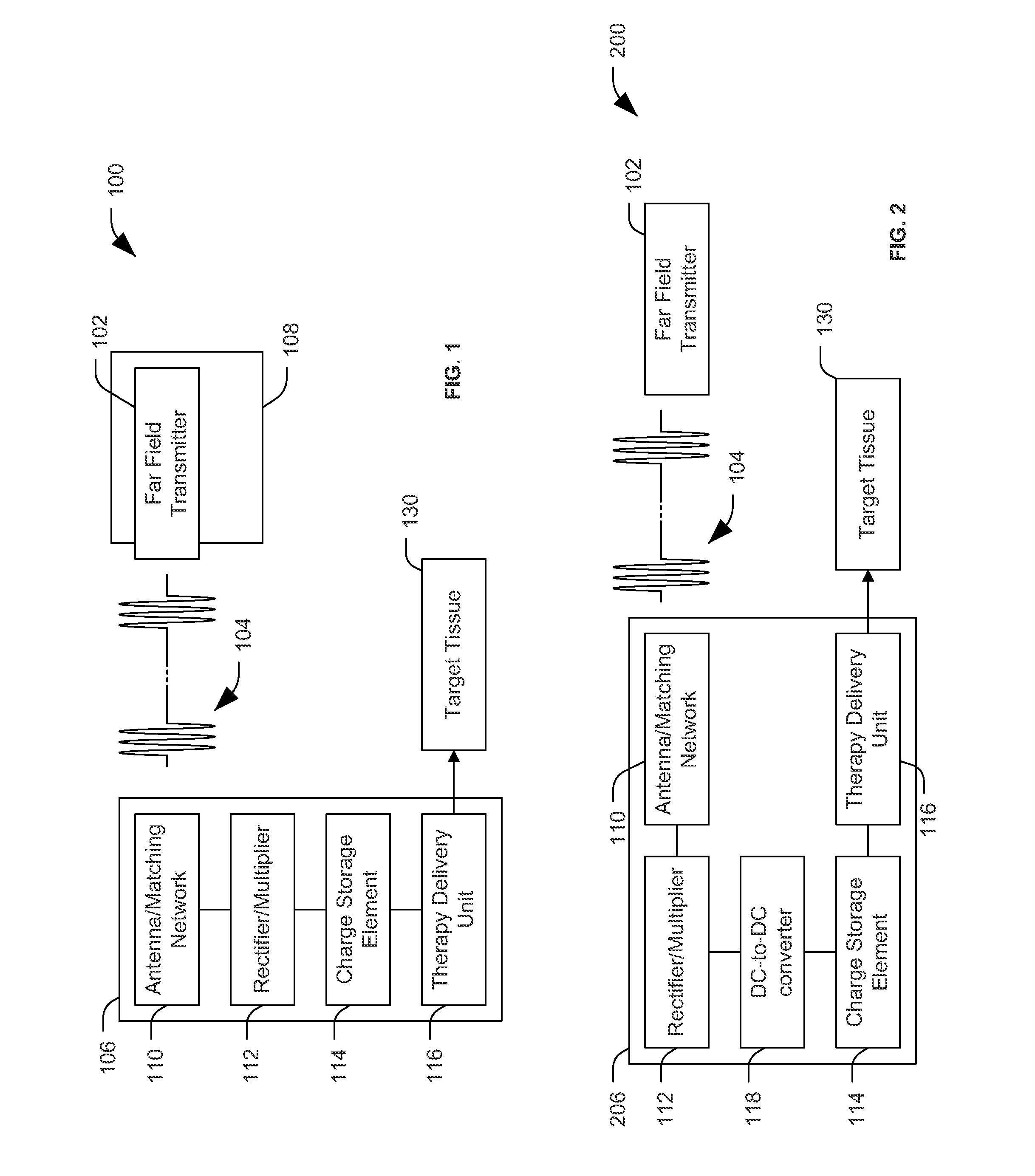
[0040]FIG. 2 is a block diagram of a second particular embodiment of a system 200 including an implantable medical device 206. The implantable medical device 206 includes a number of elements in common with the implantable medical device 106 of FIG. 1. For example, in the embodiment illustrated in FIG. 2, the implantable medical device 206 includes the antenna and matching network 110, the voltage rectifier and voltage multiplier 112, the charge storage element 114 and the therapy delivery unit 116, each of which operates as explained with reference to FIG. 1
[0041]The implantable medical device 206 may include a DC-to-DC converter 118 coupled to the voltage rectifier, coupled to the voltage multiplier, or coupled to the rectifier / multiplier 112. In one instance, the DC-to-DC converter 118 can be a boost converter used to step-up the voltage. In a further instance, the DC-to-DC converter 118 can be a step-up regulator. The DC-to-DC converter 118 may be configured to receive output of...
third embodiment
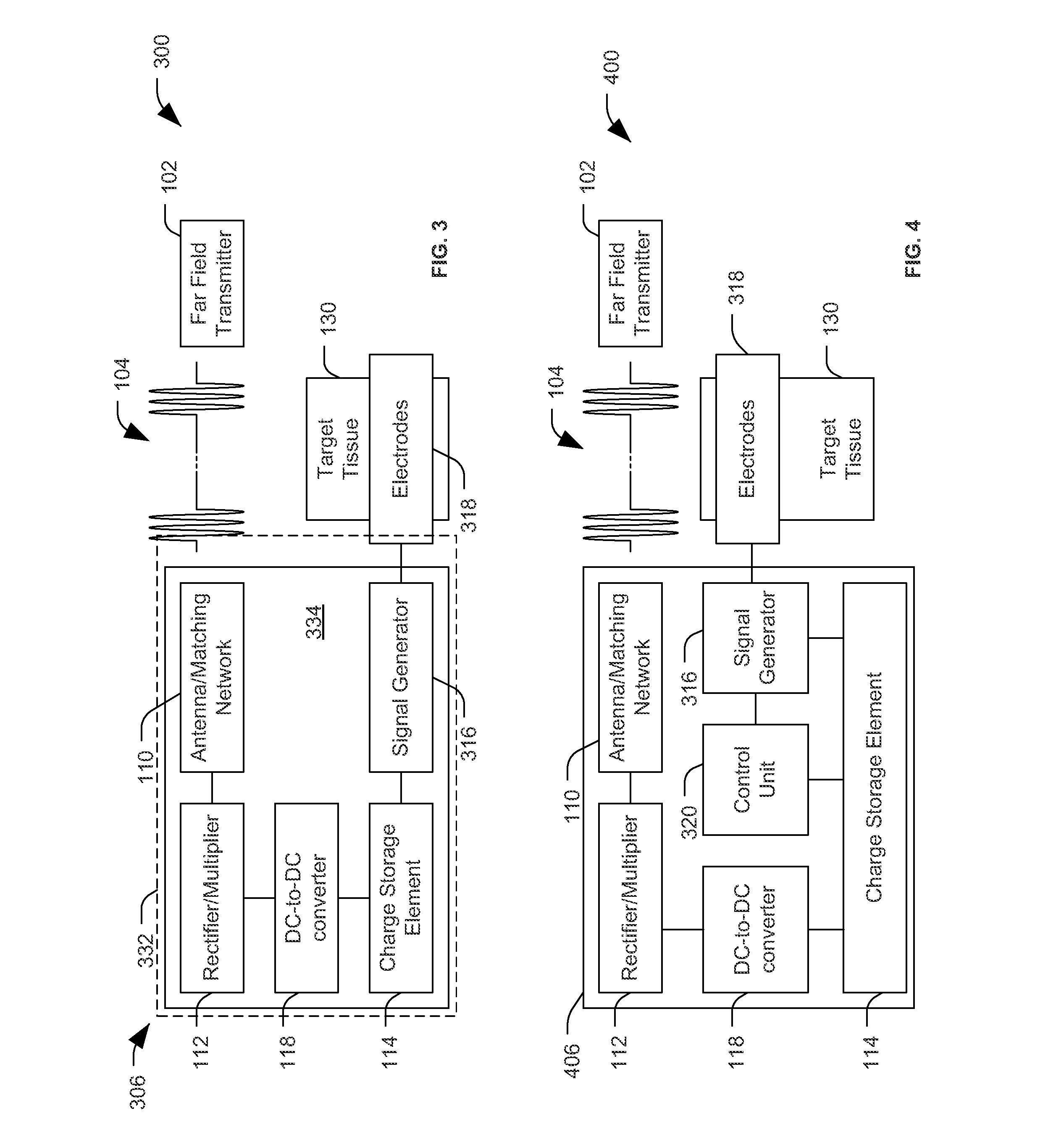
[0044]FIG. 3 is a block diagram of a third particular embodiment of a system 300 including an implantable medical device 306. The implantable medical device 306 includes a number of elements in common with the implantable medical device 206 of FIG. 2. For example, in the embodiment illustrated in FIG. 3, the implantable medical device 306 includes the antenna and matching network 110, the voltage rectifier and voltage multiplier 112, the DC-to-DC converter 118, the charge storage element 114 and the therapy delivery unit 116, each of which operates as explained with reference to FIGS. 1 and 2.
[0045]In the implantable medical device 306, the therapy delivery unit 116 is a signal generator 316. The signal generator 316 may be operative to be electrically coupled to one or more electrodes 318. The electrode(s) 318 may be configured to be positioned in proximity to, or attached to, the target tissue 130 of the patient to provide electrical stimulation to the target tissue 130. The elect...
fourth embodiment
[0048]FIG. 4 is a block diagram of a fourth particular embodiment of a system 400 including an implantable medical device 406. The implantable medical device 406 includes a number of elements in common with the implantable medical device 306 of FIG. 3. For example, in the embodiment illustrated in FIG. 4, the implantable medical device 406 includes the antenna and matching network 110, the voltage rectifier and voltage multiplier 112, the DC-to-DC converter 118, the charge storage element 114 and the signal generator 316, each of which operates as explained with reference to FIGS. 1-3. Although not specifically identified in FIG. 4, components of the implantable medical device 406 may be coupled to or formed on a flexible circuit board, such as the flexible circuit board 334 of FIG. 3. Additionally or in the alternative, the implantable medical device 406 may include, be coupled to or be embedded within a nerve wrap, such as the nerve wrap 332 of FIG. 3. Alternately, the implantable...
PUM
 Abstract
Description
Claims
Application Information
 - R&D
- Intellectual Property
- Life Sciences
- Materials
- Tech Scout
- Unparalleled Data Quality
- Higher Quality Content
- 60% Fewer Hallucinations
Browse by: Latest US Patents, China's latest patents, Technical Efficacy Thesaurus, Application Domain, Technology Topic, Popular Technical Reports.
© 2025 PatSnap. All rights reserved.Legal|Privacy policy|Modern Slavery Act Transparency Statement|Sitemap|About US| Contact US: help@patsnap.com


