
Fluid purification and sensor system

a sensor system and fluid technology, applied in the field of fluid purification apparatus, can solve the problems of poor performance below 260 nm, short operating life and long warm-up time, and toxic materials in mercury lamps

Inactive Publication Date: 2013-01-17
SHARP KK
View PDF3 Cites 29 Cited by
  • Summary
  • Abstract
  • Description
  • Claims
  • Application Information

AI Technical Summary

Benefits of technology

The patent text describes the use of UV-C laser technology to quickly kill bacteria and improve water quality. The high efficiency of the UV-C laser wavelength makes it excellent for destroying bacteria and is also highly absorbed by contaminated water. The use of focused and collimated laser beams allows for effective treatment of water and detection of microorganisms. The same light source is used for both visible and UV laser beams, reducing costs and power consumption.

Problems solved by technology

However, mercury lamps contain toxic material, tend to have short operating lifetimes and long warm-up times. An alternative UV light source currently under development is the UV semiconductor light emitting diode (LED).
The current drawbacks to using UV LEDs are again lifetime issues, their poor performance below a wavelength of 260 nm and their inability to provide a collimated beam or tightly focused light spot.
The use of laser wavelengths down to 200 nm are specified; however, no mention of air treatment is made in this patent, and the system does not provide treatment of the particles.
The system does not provide sensing.
However, this system has micro-organism sensing which is separate from the water treatment zone, and a laser is not used for the sensing of micro-organisms.
Both of these issues will increase the size and cost of such a system.
Again, the size and cost of such a system are likely to be problematic.
Also, the sensitivity and range of the detector will be limited in this device.

Method used


Image

  • Fluid purification and sensor system
  • Fluid purification and sensor system
  • Fluid purification and sensor system

Examples


example 1

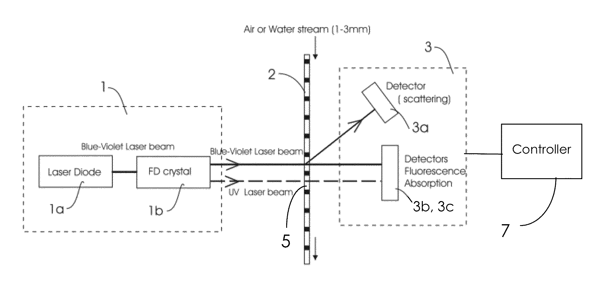
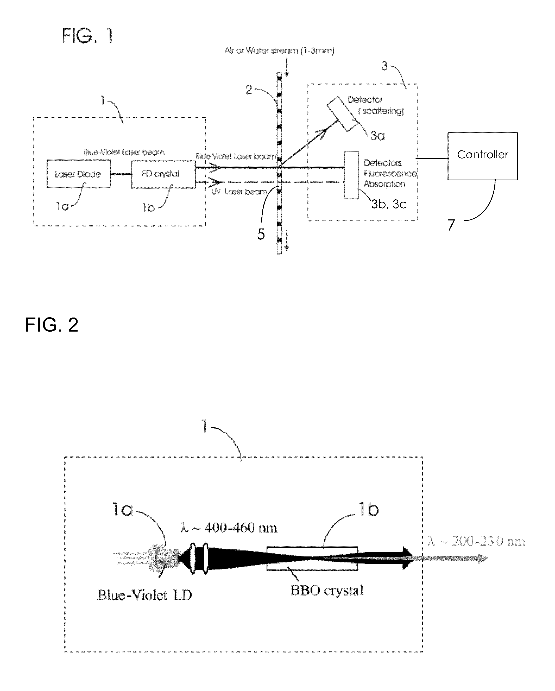
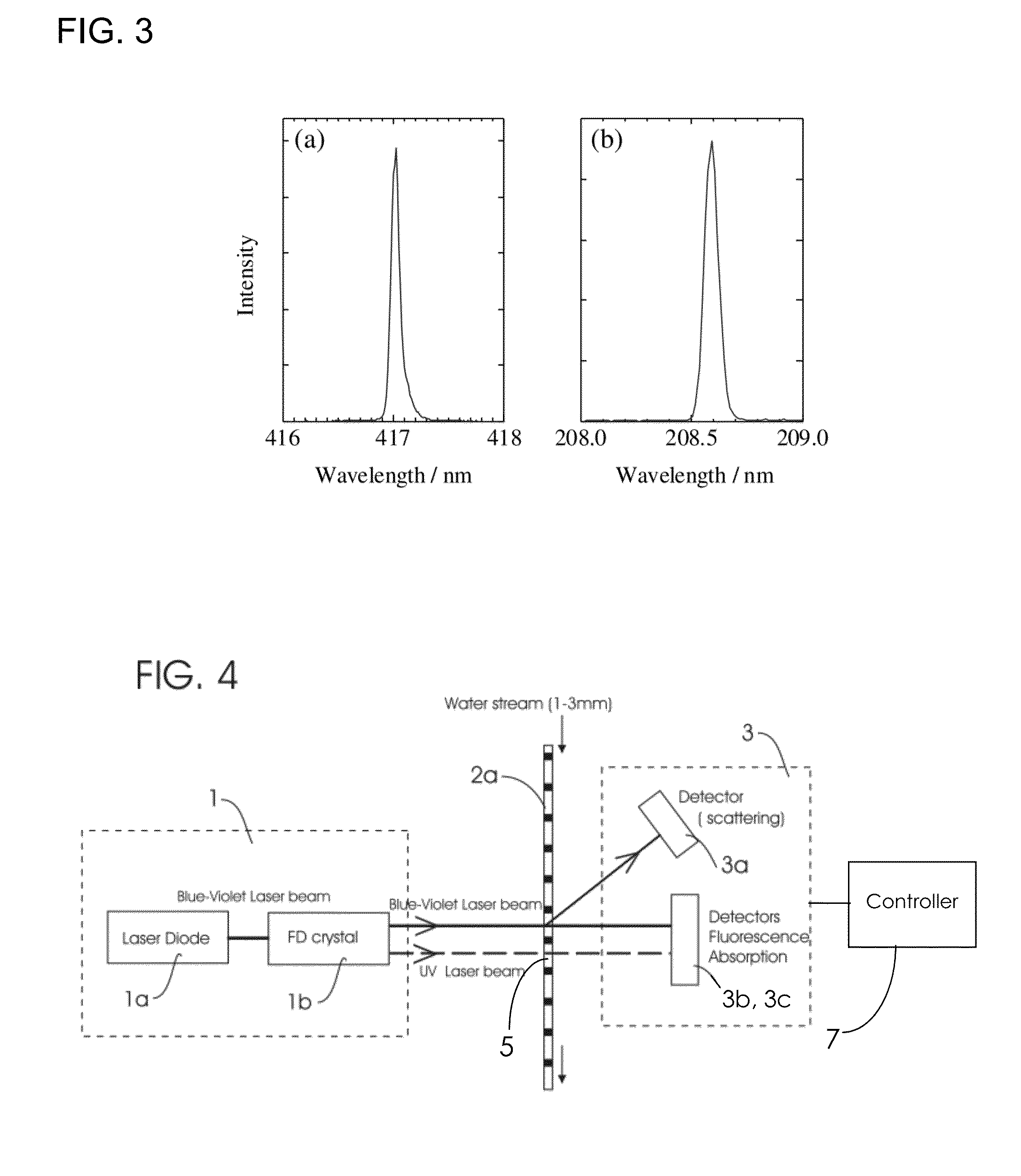
[0076]An exemplary preferred embodiment of the present invention is now described with reference to FIG. 4. The system illustrated in FIG. 4 includes a conduit 2a that provides a flow path through which a steady flow of water passes. A conduit diameter in the range 1 to 10 mm is preferred, and 3 mm is most preferred. A water flow in the range 0.1 to 3 litres per minute is preferred, and 1 litre per minute is most preferred. The conduit contains an optical window region 5 that is transparent to light in the wavelength range between about ultraviolet and infrared, and thus is transparent to wavelengths of light of the first blue-violet laser light beam and the second ultraviolet laser light beam. The optical window region 5, for example, may be crystal quartz.

[0077]The pair of laser beams provided by the dual wavelength laser component 1 are split and then directed onto the water flow via the optical window region. The UV laser beam typically will be absorbed by any biological particl...

example 2

[0081]Another exemplary preferred embodiment of the disclosed system is illustrated in FIG. 5. The embodiment of FIG. 5 includes conduit 2b that provides a flow path through which a steady flow of air passes. A conduit diameter in the range 1 to 10 mm is preferred, and 3 mm is most preferred. An air flow in the range 0.1 to 3 litres per minute is preferred, and 1 litre per minute is most preferred. The conduit contains an optical window region 5 that is transparent to light in the wavelength range between ultraviolet and infrared, and thus is transparent to wavelengths of light of the first blue-violet laser light beam and the second ultraviolet laser light beam. The optical window region 5, for example, may be crystal quartz.

[0082]The pair of laser beams provided by the dual wavelength laser component 1 are split and then directed onto the air flow via the optical window region. The UV laser beam typically will be absorbed by any biological particles or micro-organisms in the air c...

example 3

[0086]Another exemplary preferred embodiment of the disclosed system is illustrated in FIG. 6. The embodiment of FIG. 6 includes a vessel 4 which is periodically filled and emptied with a volume of air or water, and in which the volume of air or water is held for germicidal treatment and detection. A vessel volume in the range 10 to 1000 mm3 is preferred, and 125 mm3 is most preferred. The vessel contains optical window regions 6 that are transparent to light in the wavelength range between ultraviolet and infrared, and thus is transparent to wavelengths of light of the first blue-violet laser light beam and the second ultraviolet laser light beam. The optical window region 6, for example, may be crystal quartz.

[0087]The pair of laser beams provided by the dual wavelength laser component 1 are split and then directed onto the air or water volume via the optical window region. The UV laser beam typically will be absorbed by any biological particles or micro-organisms in the air / water...


PUM


Abstract

A system and method are disclosed for the simultaneous optical disinfection and detection of biological particles in a flowing fluid, such as air or water, medium. A light source for irradiating the flowing medium is a dual wavelength laser element simultaneously emitting a visible laser beam and an ultraviolet laser beam. In particular, a laser diode may generate a first visible laser light beam, and a second ultraviolet laser light beam may be generated by passing the first laser light beam through a frequency doubling crystal. Optical detectors measure scattering, fluorescence and / or transmission of the laser light beams from the air or water medium to determine the presence of biological particles in real-time.

Description

TECHNICAL FIELD[0001]The present invention relates to an apparatus for the treatment of a fluid, such as for example air or water, and the detection of fluid contamination. In particular, the present invention relates to the use of a dual wavelength emitting laser in an apparatus for the treatment of air or water and the detection of airborne or waterborne contamination. The invention may be applied to a product which purifies air and confirms whether or not the air is safe to breathe. The invention also may be applied to a product which purifies drinking water and confirms whether or not the water is safe to drink.BACKGROUND ART[0002]There is an ever increasing need for clean and safe air to breathe and water to drink, particularly in heavily populated countries or regions throughout the world. A major, high-volume, application for compact solid-state deep ultraviolet (UV-C) light sources is for chemical-free sterilisation of air or water. UV-C light causes permanent physical damag...

Claims


Application Information

Patent Timeline
IPC IPC(8): G01J1/42G01J1/58
CPCC02F1/32G01N2015/1438G01N15/1434C02F2201/326C02F1/30C02F2201/3222C02F2201/3226G01N15/147
Inventor HOOPER, STEWART EDWARDSMEETON, TIM MICHAELEVANS, ALLAN
Owner SHARP KK
Learn More