Drying System having a Thermal Engine

a drying system and thermal engine technology, applied in drying machines, drying machines with progressive movements, lighting and heating apparatus, etc., can solve the problems of electrical energy utility failures that occur occasionally, and achieve the effect of improving or optimizing the total system efficiency, reliably and economically

Active Publication Date: 2013-01-17
DUERR SYST AG
View PDF18 Cites 28 Cited by
  • Summary
  • Abstract
  • Description
  • Claims
  • Application Information

AI Technical Summary

Benefits of technology

[0005]It is an object of the invention to provide a system for heating-up components, which can be operated reliably and economically even during a temporary disconnection of the system from a public power grid and / or for which the total system efficiency can be increased or optimized.

Problems solved by technology

There, a failure occasionally occurs in the utilities or power grids for electrical energy.

Method used


Image

  • Drying System having a Thermal Engine
  • Drying System having a Thermal Engine
  • Drying System having a Thermal Engine

Examples


Embodiment Construction

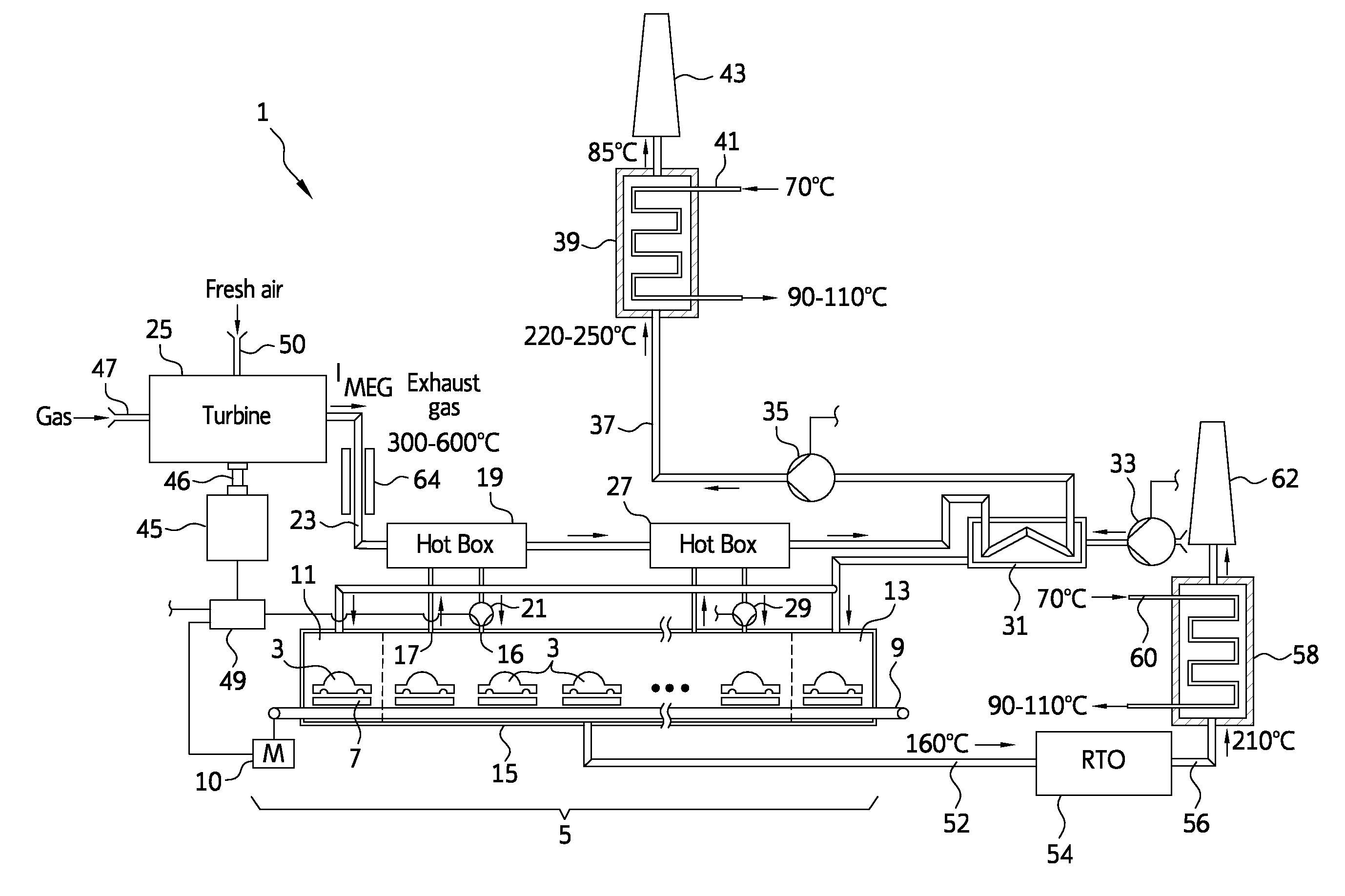
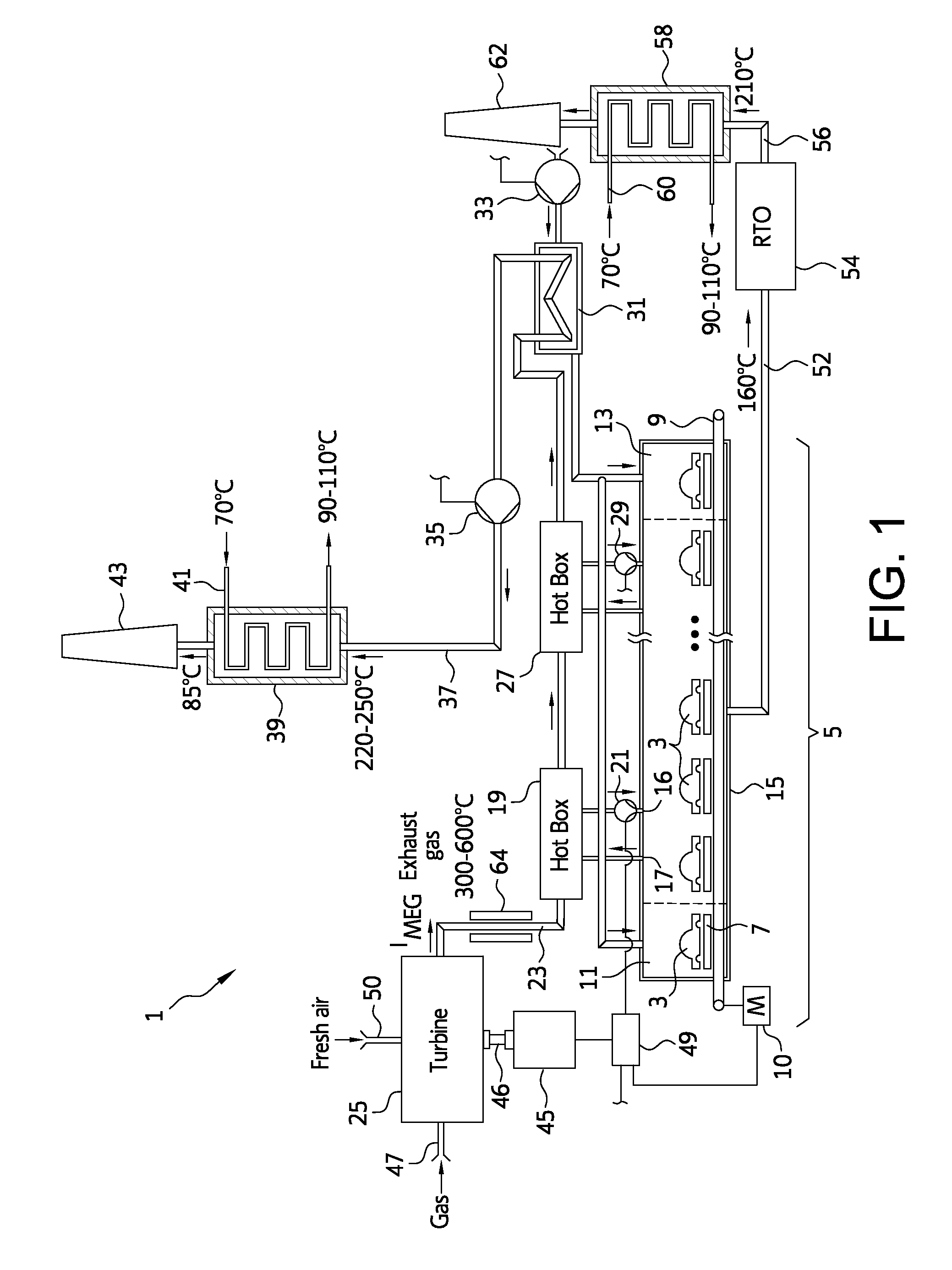
[0026]The system 1 shown in FIG. 1 for drying workpieces is designed in particular for vehicle bodies 3 (or parts thereof) and comprises a cabin that is formed as a drying tunnel 5 or as a drying cabin. The drying tunnel 5 has a substantial heat demand, such that sensible heat has to be transferred to the drying tunnel from the outside at a given, with respect to the ambient conditions significantly increased, temperature level. The invention is therefore described using a plant for drying vehicle bodies as an example. In modified exemplary embodiments, a system in accordance with the invention is provided as a plant for tempering, drying, hardening and / or irradiating, but in particular for the heating-up of large metallic workpieces. Other suitable workpieces, besides vehicle bodies (or parts thereof), are large-volume systems with comparably large heat capacities, which undergo a treatment having an increased heat demand. In accordance with the teachings of the invention, the so-c...


PUM


Abstract

A system for drying vehicle bodies and/or for controlling the temperature thereof. The system includes a cabin and has a heater for heating hot air for the cabin. The system is equipped with a mechanical energy-consuming device, for example, a generator and/or a fan. The heater contains at least one heat exchanger. The hot exhaust gas of a thermal engine can be supplied to the heat exchanger. The thermal engine is coupled to the mechanical energy-consuming device, for example, the generator, so as to move together. Because of the coupled movement, mechanical energy can be transmitted from the thermal engine to the mechanical energy-consuming device.

Description

CROSS REFERENCE TO RELATED APPLICATIONS[0001]This application is a continuation-in-part application of international patent application PCT / EP 2011 / 051094, filed Jan. 26, 2011, designating the United States and claiming priority from German application 10 2010 001 234.3, filed Jan. 26, 2010, and the entire content of both applications is incorporated herein by reference.FIELD OF THE INVENTION[0002]The invention relates to a system for the heating-up of, in particular metallic, workpieces, specifically of vehicle bodies, comprising a cabin, a heating system for heating intake air for the cabin, as well as a consumer of mechanical energy.BACKGROUND OF THE INVENTION[0003]Such a system is known from EP 1 302 737 B1, which describes a painting or coating plant for vehicle bodies, which include a drying module with a heating-up cabin for drying freshly painted or coated vehicle bodies. To this end, hot air can be circulated in the drying module with the aid of a fan. The circulated hot ai...

Claims


Application Information

Patent Timeline
Patent Type & Authority Applications(United States)
IPC IPC(8): F26B23/00F26B7/00
CPCF26B15/14F26B2210/12F26B23/022F26B23/001Y02P70/10
Inventor WESCHKE, JUERGENWIELAND, DIETMARJOST, JUERGEN
Owner DUERR SYST AG
Why Eureka
Try Eureka