
Batch-wise operated retort using temporary storage of heat

Inactive Publication Date: 2013-01-10
SIEMONS ROLAND
View PDF6 Cites 14 Cited by
  • Summary
  • Abstract
  • Description
  • Claims
  • Application Information

AI Technical Summary

Benefits of technology

The patent application describes a system that uses a heat exchanger to transfer heat instead of a temporary heat storage. The temporary heat storage is designed to accumulate heat quickly and release it later, while the heat exchanger operates in a stationary manner. The system also includes a control system to manage the heat transfer process. The system was developed to optimize the process of pyrolysis, which involves the thermal decomposition of biomass. The patent text also mentions a previous patent application that also discusses the use of a heat exchanger instead of temporary heat storage.

Problems solved by technology

Therefore, the instantaneous production of the combustible process fluid cannot be controlled independently of the heat requirement of the retorting process.
In addition, the release of the combustible process fluid by the substance cannot be controlled directly (i.e., in real-time), but only with a substantially delayed response through controlling the heat flow to or from the retort.
Storing the heating fluid itself for future use is not without difficulties.
Valves and conduits of an arrangement for storing the heating fluid may get clogged as a result of partial condensation of the heating fluid.

Method used


Image

  • Batch-wise operated retort using temporary storage of heat
  • Batch-wise operated retort using temporary storage of heat
  • Batch-wise operated retort using temporary storage of heat

Examples


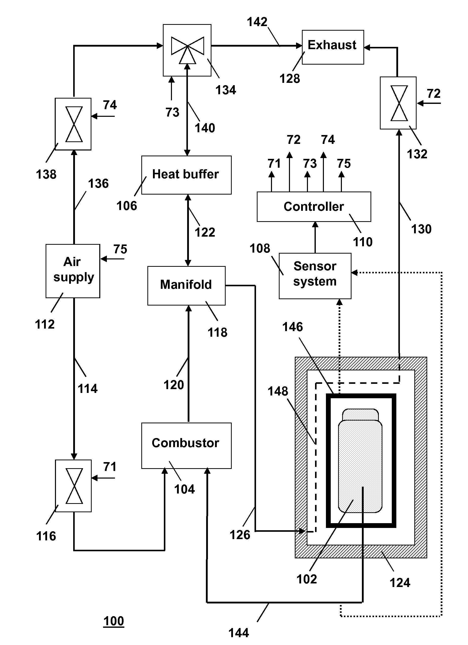
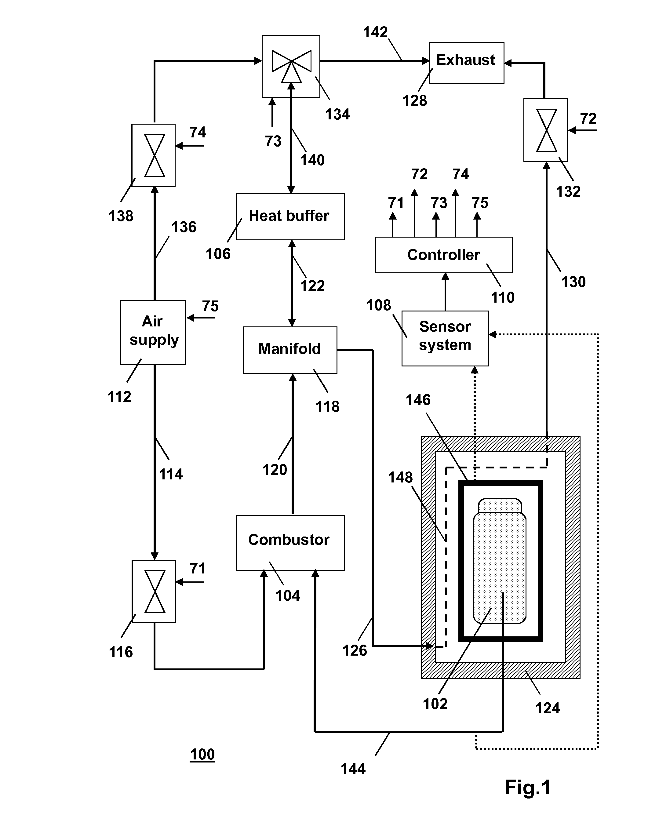
embodiment 100

[0129]Assume that operation of the embodiment 100 is to be started up. In an example scenario, first the heat buffer 106 is heated up using, e.g., an additional fuel or an external heat source (not shown), e.g., solar energy. When the heat buffer 106 has reached a suitably high temperature, the retort 102 that contains a first batch of the substance to be processed, is mounted within the container 124.

[0130]In a first step, after the retort 102 has been mounted in the container 124, the second valve 132 and the fourth valve 138 are opened, and the third valve 134 is switched so as to provide a passageway from the sixth pipe 136 to the seventh pipe 140. Then, the air supply 112 creates a flow of cold air to the heat buffer 106 via the sixth pipe 136 and the seventh pipe 140. The cold air passes through the heat buffer 106. Heat is transferred from the heat buffer 106 to the cold air, and the cold air heats up. Hot air exits the heat buffer 106 and is supplied to the container 124 via...

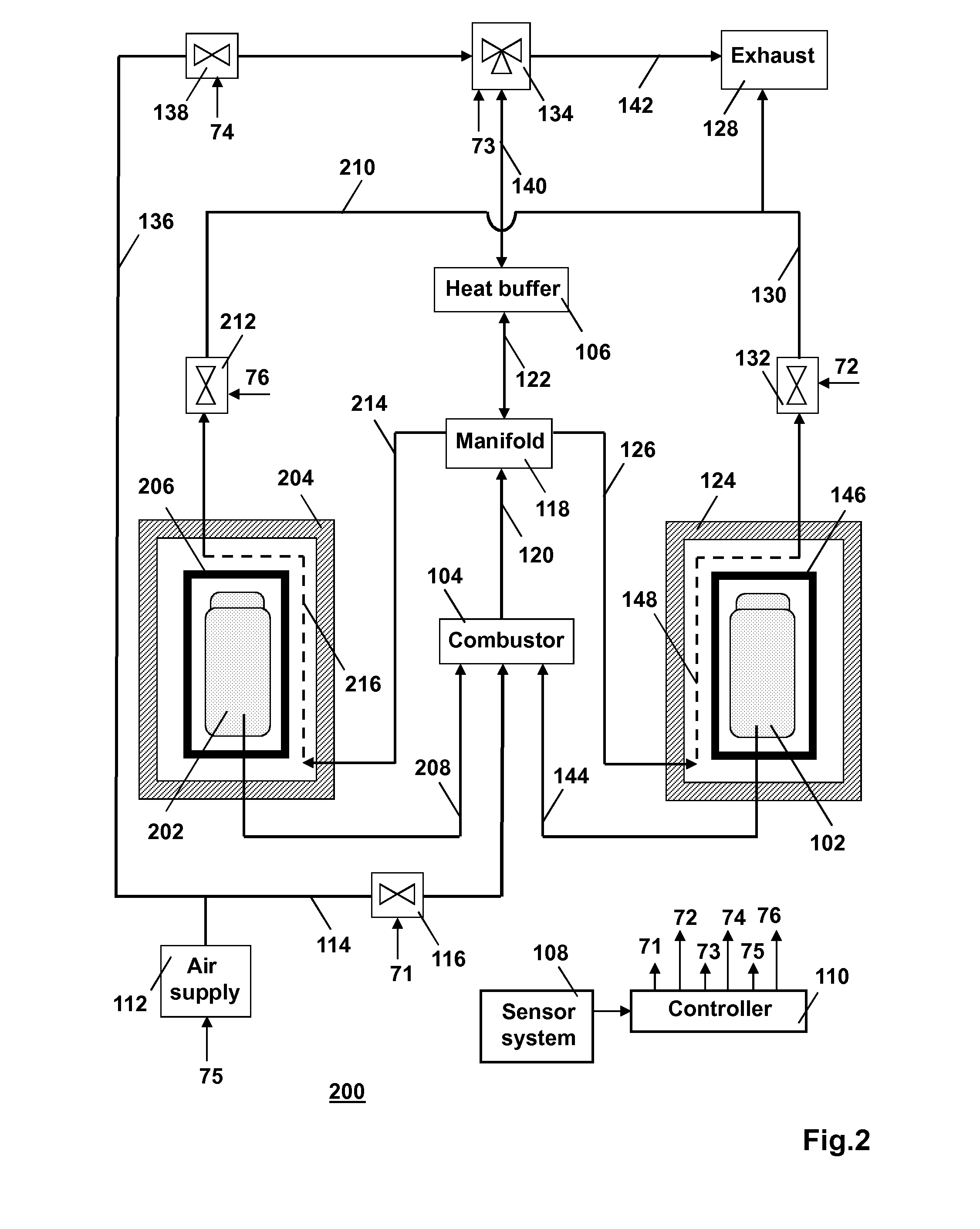
second embodiment

[0145]The retort 102 and the further retort 202 may be operated in counter-phase. That is, the second embodiment is controlled so that, when the processing of the substance in the retort 102 is in an exothermic phase, the processing of the substance in the further retort 202 is in an endothermic phase and vice versa. Alternatively, the retort 102 and the further retort 202 may be operated independently of each other.

[0146]For each individual one of the retort 102 and the further retort 202, respective endothermic phases and respective exothermic phases are distinguished. As described above with reference to the first embodiment 100, the second valve 132 rations the flow of the hot combustion fluid, or of the flow of the mixture of the hot air and the hot combustion fluid, from the manifold 118 via the container 124 to the exhaust 128. The rationing is governed according to the instantaneous heat requirement of the processing of the substance in the retort 102. Similarly, the fifth v...


PUM


Abstract

A batch of a substance, e.g., a biomass, is processed in a batch-wise operated retort under the application of heat. The substance releases a combustible process fluid during the processing. The process fluid is combusted for generating heat. The heat is supplied to the retort and / or stored in temporary heat storage in dependence on the progress of the processing for postponed heat supply to the retort.

Description

FIELD OF THE INVENTION[0001]The invention relates to a processing system for processing a substance, wherein the processing system is configured for processing the substance in subsequent batches. The invention also relates to a method of processing a substance.BACKGROUND ART[0002]An industrial retort is used 1) to contain, and 2) to transfer heat to, a substance that is being processed in the retort, 3) to prevent that the substance that is being processed is contacted with foreign matter such as air or another gas and 4) to enable controlled collection of a process fluid, e.g., a reaction vapor or a reaction liquid, that is released by the substance during the processing of the substance in the retort. The substance comprises a compound that is being processed or multiple different compounds that are being processed. The heat is transferred to the substance within the retort. The transferred heat serves to raise the temperature of the substance in the retort to a particular level,...

Claims


Application Information

Patent Timeline
IPC IPC(8): F27D21/04F24H7/00
CPCB01J6/008Y02E50/14B01J2219/00038B01J2219/0006B01J2219/00063B01J2219/00117B01J2219/00193B01J2219/002B01J2219/00204B01J2219/00229C10B47/06C10B53/02C10B53/06C10B53/07C10B57/00F23G5/0273F23G7/068B01J2219/00029Y02P20/143Y02E50/10
Inventor SIEMONS, ROLAND
Owner SIEMONS ROLAND
Learn More