Method for controlling entertainment equipment based on performer position

a technology of entertainment equipment and position, applied in the direction of gain control, subscriber station connection selecting arrangement, indirect connection, etc., can solve the problem of increasing the cost of potential for human error in the live sound production process, vocalists singing out of tune with the instrumental sound, and comb filtering effect which may be undesirabl

Inactive Publication Date: 2013-01-10
HEJNICKI THOMAS
View PDF5 Cites 20 Cited by
  • Summary
  • Abstract
  • Description
  • Claims
  • Application Information

AI Technical Summary

Benefits of technology

[0014]In its broadest sense, the invention is a combination radio frequency identification (“RFID”) and entertainment equipment control system that both: (a) determines either (i) relative spacing between a particular individual and a particular transducer, power-adjuster or other outputting device (e.g., a microphone, speaker, light source, amplifier, attenuator, etc) or (ii) the location of an individual within an RFID-mapped stage area; and (b) controls the operation or treatment of the output of the device based upon that relative spacing or location determination. Its inventors anticipate that the present system will be used, primarily, to mute a stationary microphone—by either disabling the microphone itself or by attenuating its output signal—when the specific performer to whom the stationary microphone is assigned has moved beyond a threshold distance from it, They also anticipate the system will be used to similarly mute a mobile microphone when it is transported out of or into a particular area of the performance stage. And in addition to audio control applications, they anticipate that the system will be used to control operability of light sources and pyrotechnic initiators based upon the same determinations of specific performer location or relative spacing.
[0015]It is, therefore, an object of the present invention to determine whether, in the context of multiple people being within a small performance area, one specific such individual is within a predefined distance of a particular microphone or other outputting device. In one aspect of the invention, an RFID reader is attached to the outputting device and uniquely coded RFID tags are worn by each of multiple on-stage performers. So, when a tag-wearing performer is positioned within the reading zone of a reader, the reader specifically recognizes both his presence and his specific identity by its reading of data stored on his RFID tag.
[0016]It is another object of the invention to provide real-time monitoring of the location of one or more microphone-carrying performers within a performance area. In another aspect of the invention, multiple RFID readers are strategically mapped throughout a performance area, and unique RFID tags are both worn by each of multiple performers and attached to each microphone. So, as performer brings his microphone to within the reading zone of a reader, the reader recognizes that presence by its reading of unique identifying data stored on the tags worn by him and attached to his held or worn microphone.
[0017]It is another object of the invention to control the operation of an outputting device based on these spacing and location recognitions. In another aspect of the invention, the RFID readers are all connected to a computer which is programmed to control at least one outputting device (e.g., microphone, loudspeaker, amplifier, attenuator, light emitter, pyrotechnic initiator) based upon the positioning a particular RFID tag within the mapped area or relative to a particular RFID reader. For example, where an RFID reader is attached to a stationary microphone (“mic-1”) and an RFID tag is worn by a vocalist, the computer may be programmed to mute mic-1 so long as the vocalist's worn tag is not close enough to mic-1 be read by its attached reader. For another example, where an RFID reader is attached to a main loudspeaker (“speaker-1”), a first RFID tag is attached to a mobile microphone (“mic-2”), and a second tag is worn by a vocalist (e.g., tucked inside a garment pocket or attached to a lanyard) the computer may be programmed to mute disable speaker-1 so long as both tags are close enough to it to be read by the attached reader.
[0018]It is another object of the present invention to control treatment of the output of an outputting device (e.g., routing, power level, etc.). For example, the computer may be programmed to attenuate—even completely—the sound signal output of the aforementioned mic-2 before that signal is routed to speaker-1, Similarly, microphone signal output can be amplified to a predetermined level based on an RFID tag proximity determination.
[0019]It is yet another object of the present invention to control the operation of light banks, lasers, fireworks and other show effects based upon similar RFID proximity determinations.

Problems solved by technology

Without a stage monitor system in place, a vocalist performing in a loud arena might be unable to hear his own vocals until the amplified sound waves transmitted by speakers directed at the audience have reflected off of a distant arena wall and traveled back to the stage—potentially causing the vocalist to sing out of tune with the instrumental sound.
This, of course, increases the cost of and potential for human error in the live sound production process.
Because sound waves produced by one source travels different distances to reach different microphone positions, if the same sound is detected by multiple microphones, similar audio signals transmitted by those microphones may arrive at a mixing device at different times to create a comb filtering effect which may be undesirable.
As the microphone count increases, the potential gain before feedback occurs is reduced—limiting amplification of the microphones—and the potential for bleed is increased.
However, the proposition of having a sound engineer manually mute or fade different microphones on-the-fly in attempt to both filter out unwanted sound and maximize acoustical bandwidth can be overly tedious and problematic.
Yet, since an engineer cannot always anticipate the occurrence and timing of such things, some audio of that nature may be lost simply due to it being generated at moments when certain microphones happen to be muted or faded out.
However, on the negative side, it can also have the effect of chopping off the end of a performer's vocals as they trail off and drop below the pre-set gate threshold—especially if that threshold must he set relatively high due to there being loud crowd noise.
Therefore, even though it relieves some human burden, the noise gate is not always an ideal tool for use in live performances.
Furthermore, because the noise gate does not distinguish sources of vocal or instrumental sound, it is ineffective in preventing a sound system from blocking or otherwise muting sound based on its specific source, rather than on its level.
Still, while infrared technology is effective for identifying the proximity of a human body and can be used for the purpose of enabling and disabling a microphone according to that proximity, like the noise gate, it is incapable of distinguishing different human bodies from one another.
Consequently, infrared technology could not facilitate, for example, a concert program in which a microphone is supposed to function only when a specific individual performer is holding or standing right before it (as opposed to another person holding it or being in proximity).
In addition, since incandescent light sources produce infrared radiation, concert lighting effects may provide false indications to the sensors of an infrared-based microphone control system and cause controlled microphones to function (or not) at inappropriate times.

Method used


Image

  • Method for controlling entertainment equipment based on performer position
  • Method for controlling entertainment equipment based on performer position
  • Method for controlling entertainment equipment based on performer position

Examples


Embodiment Construction

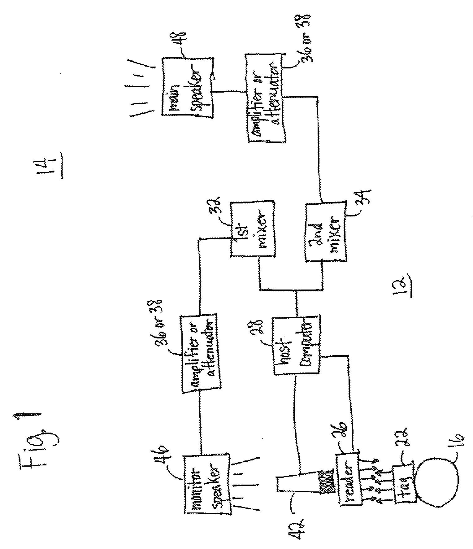
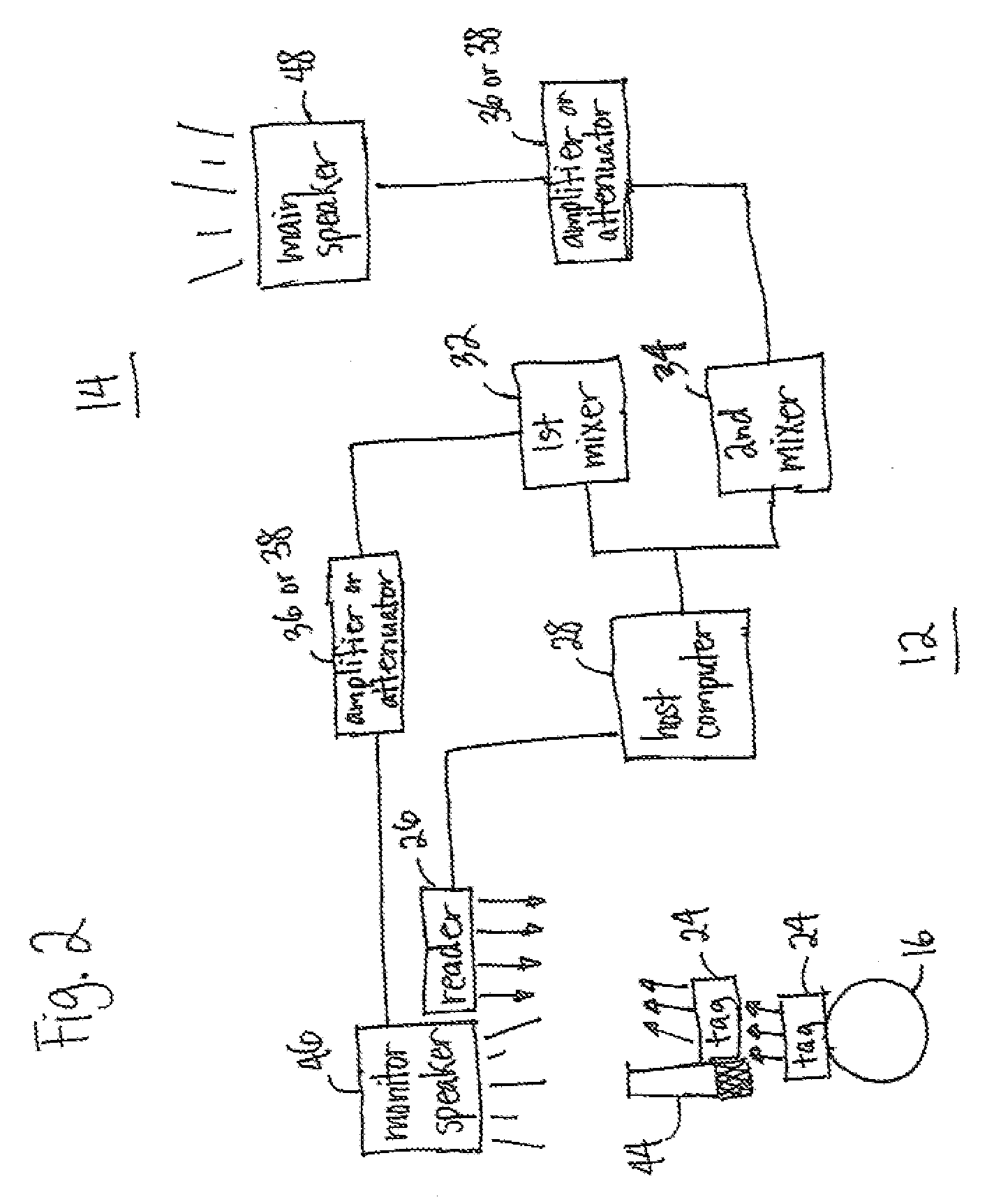
[0024]This disclosure, as defined by the claims that follow and as presented by way of example in the accompanying drawings, relates to an RFID-based entertainment equipment control system and method for it use. The present inventors anticipate that this system will be used in controlling the operability or output of a variety of transducers, power adjusters and other outputting devices, including loudspeakers, amplifiers, attenuators, light emitters, pyrotechnic launchers and conceivably other apparatuses commonly used in live entertainment productions. So, although the following discussion will primarily focus on microphones (or their audio signal output) as being the particular devices controlled according to location or distance determinations made with RFID technology, one should remain aware that the functionality and / or output of other types of entertainment equipment could be controlled according to similar logic and in similar fashion.

[0025]The present entertainment control...


PUM


Abstract

A method and system for automatically and reliably controlling equipment for outputting sound and, potentially, lighting, pyrotechnics and other effects in live entertainment productions based upon the real-time physical location of one or more specific performers within a performance area in either an absolute sense or relative to a controlled article of equipment. The system includes a radio frequency identification subsystem and an equipment control subsystem.

Description

[0001]The hardware composition of an audio system for delivering live musical content in a concert environment usually depends on a host of factors including, but not limited to: venue size and configuration, stage or performance area size and configuration; the number of on-stage performers, the number and types of musical instruments used, the number and placement of microphones within the performance area, speaker placement and orientation, and the types of special effects to be produced during the performance, For example, while a solo artist performing in a home or small commercial venue might require a sound production system made up of no more than one microphone, an amplifier and a loudspeaker, a multi-person band performing in a large auditorium or stadium will invariably require considerably more sound equipment. In fact, modem audio systems for producing live music in larger concert venues are typically made up of dual systems: (a) a main system for projecting a mixture o...

Claims


Application Information

Patent Timeline
Patent Type & Authority Applications(United States)
IPC IPC(8): H03G3/00G06K7/01
CPCH04R3/12H04R2420/07H04R2227/001H04R27/00
Inventor HEJNICKI, THOMAS
Owner HEJNICKI THOMAS
Why Eureka
Try Eureka