
Optical film and manufacturing method thereof, liquid cristal display apparatus using the optical film

a technology of optical film and manufacturing method, applied in the direction of diffusing elements, instruments, electromagnetic radiation sensing, etc., can solve the problems of reducing the viewing angle from both sides, narrow viewing angle, and difficulty in manufacturing prism light guide plates, so as to increase assembly productivity and reduce manufacturing costs

Active Publication Date: 2013-01-10
GLOTEC
View PDF1 Cites 11 Cited by
  • Summary
  • Abstract
  • Description
  • Claims
  • Application Information

AI Technical Summary

Benefits of technology

The present invention is aimed at providing an optical sheet for a backlight unit in LCD-TVs using a printless light guide plate, which is a single sheet that reduces assembly manufacturing costs and increases productivity. The invention also provides a method of manufacturing the optical sheet and a liquid crystal display apparatus that uses the optical sheet.

Problems solved by technology

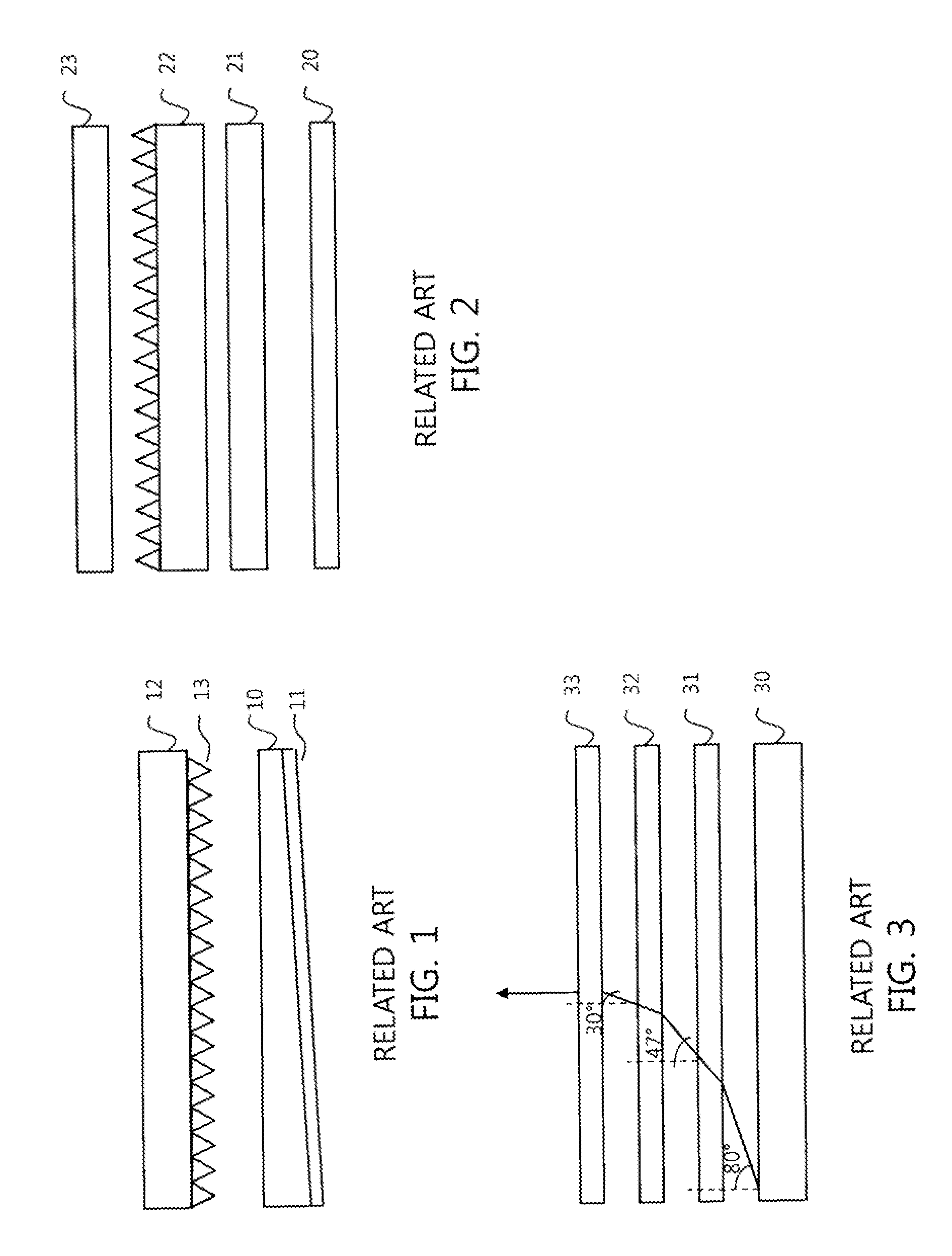
Although a single sheet on the prism light guide plate may be achieved using the prism light guide plate illustrated in FIG. 1, the viewing angle is too narrow and it is difficult to manufacture the prism light guide plate, and it is not used more but rather less. FIG. 2 schematically illustrates a backlight unit using the printless light guide plate.
However, the backlight unit for LCD-TVs uses a single horizontal prism sheet because the use of two prism sheets may increase luminance but decrease the viewing angle from both sides.
The prism sheet is problematic because prism-shaped ridges are exposed to the surface and may thus easily generate scratches upon handling or after assembly.
However, the case where the printless light guide plate is adopted in the backlight unit for LCD-TVs is problematic because a plurality of optical sheets is used, undesirably making it impossible to achieve slimness, decreasing assembly productivity and increasing the cost of the backlight unit.

Method used


Image

  • Optical film and manufacturing method thereof, liquid cristal display apparatus using the optical film
  • Optical film and manufacturing method thereof, liquid cristal display apparatus using the optical film
  • Optical film and manufacturing method thereof, liquid cristal display apparatus using the optical film

Examples


Embodiment Construction

[0021]Hereinafter, embodiments of the present invention will be more clearly understood with reference to the appended drawings.

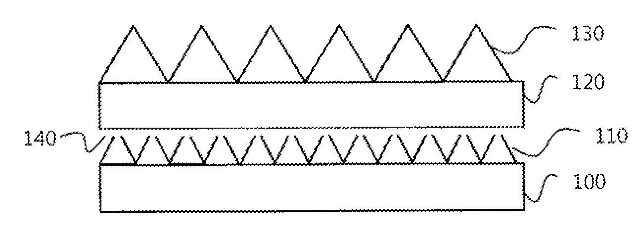
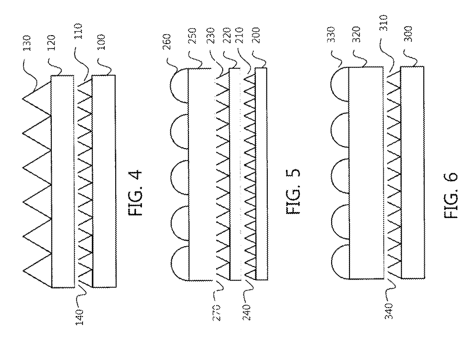
[0022]FIG. 4 is a schematic view illustrating an optical sheet having a single sheet structure for a backlight unit according to an embodiment of the present invention. As illustrated in FIG. 4, the optical sheet having a single sheet structure according to the present invention comprises a first base layer 100 comprising, as a polyethylene terephthalate (PET) film, a first PET film; a first functional layer 110 having a prism pattern formed in a first direction on the upper surface of the first base layer 100; a second base layer 120 comprising a second PET film; an adhesive layer 140 which adheres the prism pattern of the first functional layer 110 to the bottom of the second base layer 120; and a second functional layer 130 having a prism pattern formed in the first direction on the upper surface of the second base layer 120.

[0023]The optical sheet havin...


PUM

PropertyMeasurementUnit
heightaaaaaaaaaa
heightaaaaaaaaaa
heightaaaaaaaaaa

Abstract

An optical sheet having a single sheet structure for an edge-lighting backlight unit using a printless light guide plate, a method of manufacturing the same, and a liquid crystal display apparatus using the same are provided. The optical sheet having a single sheet structure includes a first prism sheet having a prism pattern formed on the upper surface thereof, and a second prism sheet having a prism pattern formed on the upper surface thereof. Further, prism ridges of the first prism sheet are attached to the bottom surface of the second prism sheet by means of an adhesive so that the prism pattern of the first prism sheet and the prism pattern of the second prism sheet are directed in the same direction.

Description

BACKGROUND OF THE INVENTION[0001]1. Field[0002]The present invention relates to an optical sheet for a backlight unit (BLU) of a liquid crystal display apparatus and a method of manufacturing the same, and a liquid crystal display apparatus using the optical sheet. More particularly the present invention relates to an optical sheet having a single sheet structure for an edge-lighting backlight unit using a printless light guide plate in a liquid crystal display apparatus, and to a method of manufacturing the same, and to a liquid crystal display, apparatus using the optical sheet.[0003]2. Description of the Related Art[0004]The light guide plates that can be used in the edge-lighting backlight units of LCDs usually fall into the two categories of a prism light guide plate, which uses only light refraction, and a non-printing light guide plate, which uses the scattering and condensation of light. FIG. 1 schematically illustrates a backlight unit using the prism light guide plate. As ...

Claims


Application Information

Patent Timeline
Patent Type & Authority Applications(United States)
IPC IPC(8): G02F1/1335B32B37/14B32B37/12G02B5/04B32B37/02
CPCG02B5/0231G02B6/0053G02B5/0278G02B5/02G02B5/04G02F1/1335
Inventor SUNG, GI SUKKIM, CHANG KUN
Owner GLOTEC
Learn More