Electronic device and method for an amplifier with resistive feedback

a technology of resistive feedback and electronic devices, which is applied in the direction of amplifiers, amplifiers with semiconductor devices/discharge tubes, low noise amplifiers, etc., can solve the problem of not being able to use resistors

Active Publication Date: 2013-01-10
TEXAS INSTR INC
View PDF4 Cites 7 Cited by
  • Summary
  • Abstract
  • Description
  • Claims
  • Application Information

AI Technical Summary

Benefits of technology

[0006]It is a general object of the invention to provide an electronic device that is a...

Problems solved by technology

Accordingly, the DC operating point of the noninverting amplifier is established by resistor R. However, in integrated semiconductor circuits, the use of a resistor is not desirable in some cases due to the comparatively large area neede...

Method used


Image

  • Electronic device and method for an amplifier with resistive feedback
  • Electronic device and method for an amplifier with resistive feedback
  • Electronic device and method for an amplifier with resistive feedback

Examples


Embodiment Construction

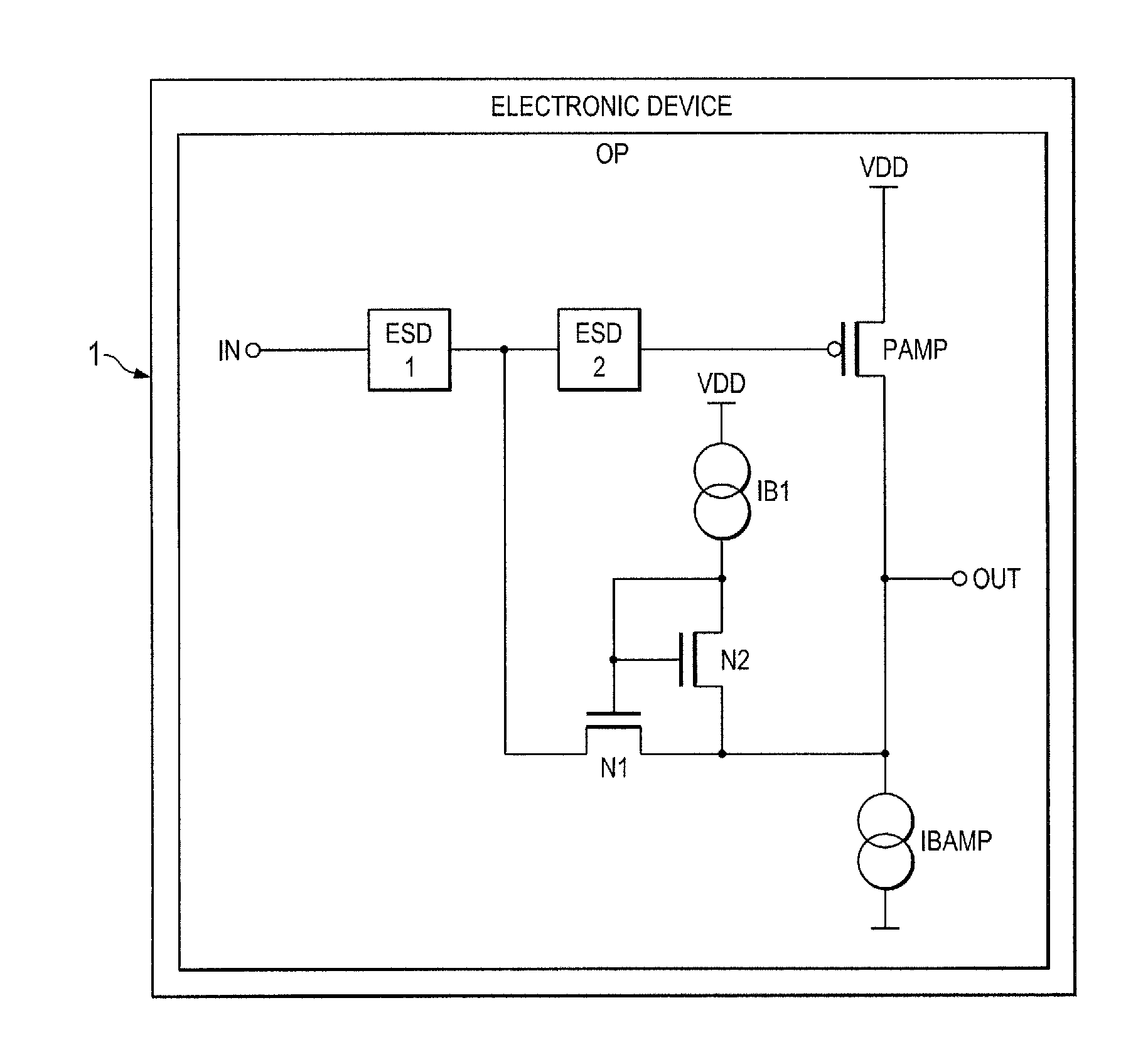
[0028]FIG. 2 shows a simplified circuit diagram of an embodiment of the invention. There is a single-transistor amplifier comprising a PMOS transistor PAMP and bias current source IBAMP coupled to supply a current through the PMOS transistor PAMP. The PMOS transistor serves as input transistor of the amplifier. The control gate of the input transistor PAMP is coupled to receive an input signal IN to be amplified. The transistor PAMP may have a transconductance (or slope) gm, which is defined by the properties (channel length and width of PAMP) and the bias current provided by IBMAP. There is a first transistor N1 which is coupled with its channel between the control gate of the input (or amplifying) transistor PAMP, i.e. the input IN of the amplifier and the output OUT of the amplifier. The control gate of the first transistor is biased with a second transistor N2, which is diode-coupled. Diode-coupled means that the gate and the drain of transistor N2 are coupled together. The sour...


PUM


Abstract

An electronic device comprising an amplifier having at least a first input transistor of a first doping type. A first transistor is coupled with a channel as a feedback path between an output of the amplifier and a control gate of the first input transistor forming an input of the amplifier. A diode-coupled second transistor is coupled with a channel between a first current source and the output of the amplifier wherein a control gate of the first transistor is coupled between the first current source and the diode-coupled second transistor and the first transistor is of a second doping type which is opposite to the first doping type of the first input transistor of the amplifier.

Description

CROSS-REFERENCE TO RELATED APPLICATIONS[0001]This patent application claims priority from German Patent Application No. 10 2011 013 107.8, filed Mar. 4, 2011, which is incorporated herein by reference in its entirety.FIELD OF THE INVENTION[0002]The invention relates to an electronic device with a resistive feedback and a method.BACKGROUND OF THE INVENTION[0003]There are numerous different applications where capacitively fed back amplifiers are required. This type of amplifier usually includes a capacitor coupled between an inverting input and the output of an operation or amplifier. Such an amplifier with a capacitive feedback requires a resistive path between the inverting input and the output of the operational amplifier in order to properly define a DC bias point of the input of the operational amplifier.[0004]FIG. 1 shows a simplified circuit diagram of a capacitively fed back non-inverting amplifier according to the prior art. There is an operational amplifier OP1 having a capa...

Claims


Application Information

Patent Timeline
IPC IPC(8): H03F1/38
CPCH03F1/523H03F3/19H03F3/45183H03F3/45475H03F2203/45728H03F2203/45512H03F2203/45528H03F2203/45544H03F2203/45674H03F2200/294
Inventor PESCHKE, CARLOMUELLNER, ERNST
Owner TEXAS INSTR INC
Why Eureka
Try Eureka