
Glossing device and image forming apparatus incorporating same

Inactive Publication Date: 2012-12-27
RICOH KK
View PDF8 Cites 8 Cited by
  • Summary
  • Abstract
  • Description
  • Claims
  • Application Information

AI Technical Summary

Benefits of technology

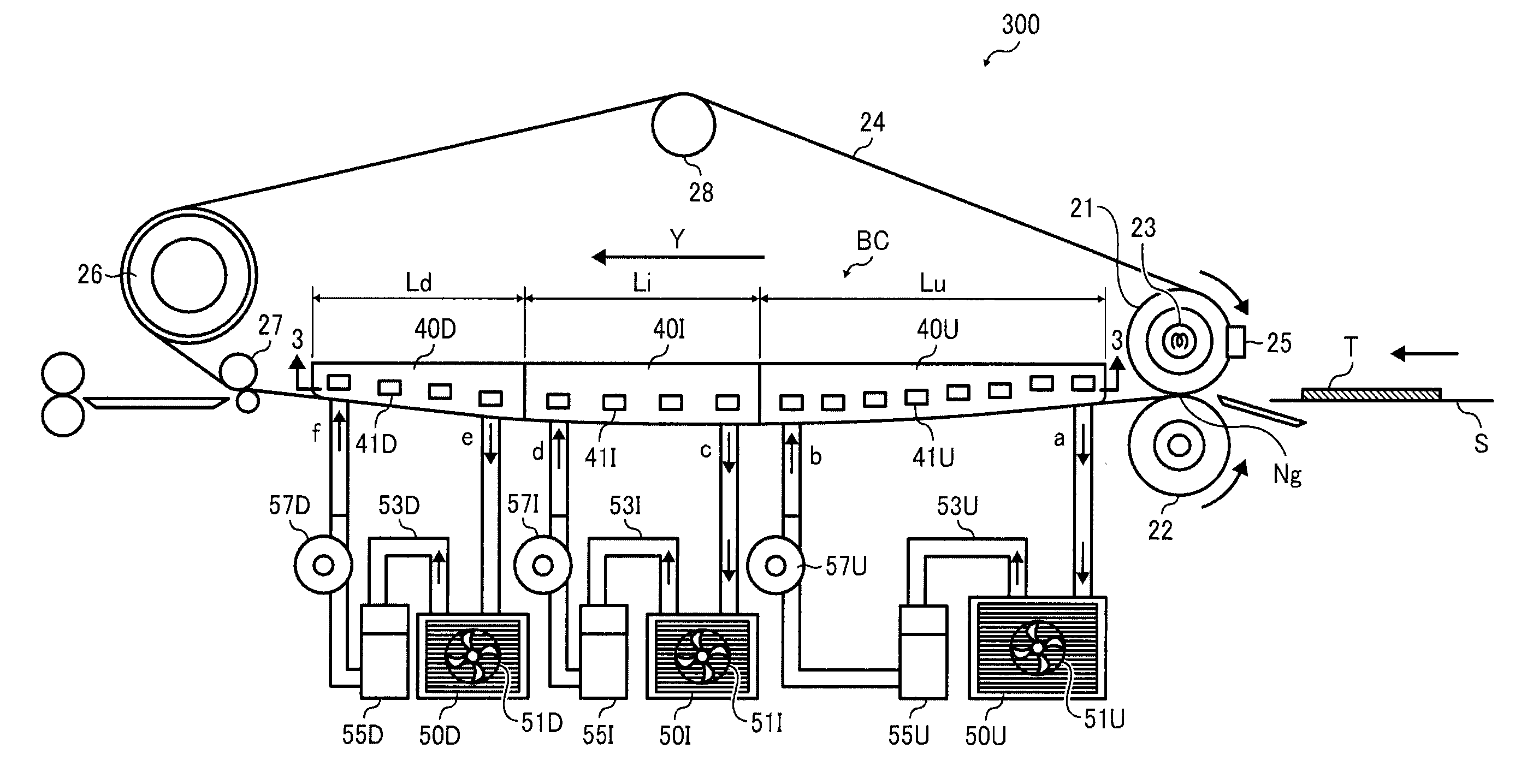
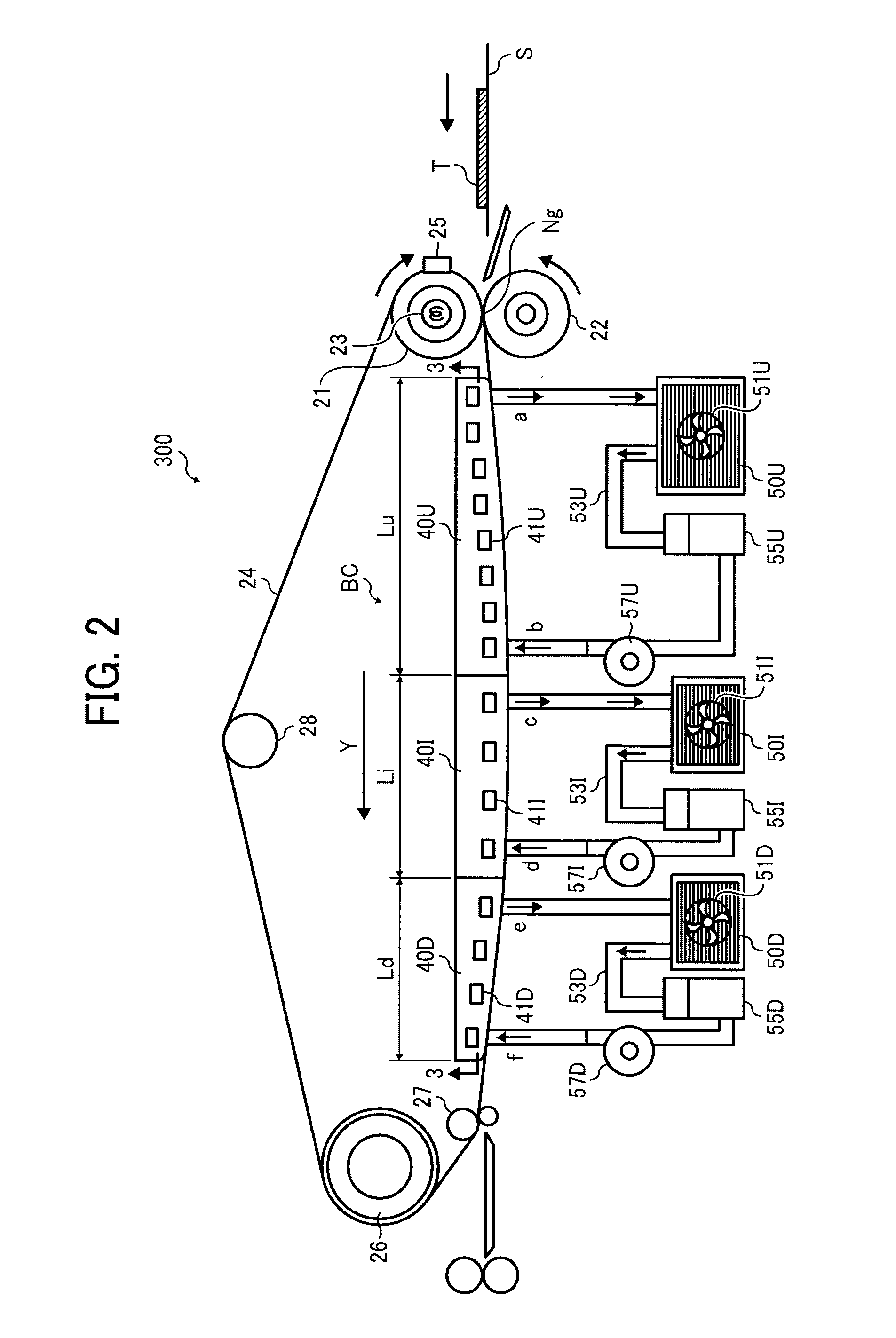
[0013]Yet still another known technique proposes a belt-based fixing device that can control an amount of compression experienced by the belt upon cooling, which employs a cooling device disposed inside the loop of the endless belt to cool the belt to a desired temperature. The cooling device includes multiple cooling members of different cooling capacities disposed in thermal contact with the belt, which are arranged with respect to each other in a longitudinal, conveyance direction of the belt such that those located upstream have lower heat capacities than those located downstream for preventing the belt from a rapid temperature change and a concomitant thermal contraction during cooling.
[0070]As used herein, the term “cooling capacity” refers to an amount of heat removed or dissipated from the cooling element through the heat dissipator per unit of time, the value of which is determined depending on various factors, such as properties of coolant in use and temperatures with which the heat dissipator is operated. For example, where the heat dissipator is constructed of a radiator using a liquid coolant, the cooling capacity of the heat dissipator may be defined by the following equation:
[0013]Yet still another known technique proposes a belt-based fixing device that can control an amount of compression experienced by the belt upon cooling, which employs a cooling device disposed inside the loop of the endless belt to cool the belt to a desired temperature. The cooling device includes multiple cooling members of different cooling capacities disposed in thermal contact with the belt, which are arranged with respect to each other in a longitudinal, conveyance direction of the belt such that those located upstream have lower heat capacities than those located downstream for preventing the belt from a rapid temperature change and a concomitant thermal contraction during cooling.

Problems solved by technology

For example, the belt cooler employed in those belt-based fixing devices is vulnerable to reduced efficiency where a large number of print jobs are sequentially processed.
Sequential processing of print jobs often results in substantial amounts of heat released to the surrounding over time.
In case of air-cooled, non-contact cooling that employs a cooling fan, heat released to the surrounding air translates into a heated air flow generated by the cooling fan, and a concomitant rise in temperature of the belt.
In case of a contact cooling system or heat sink that directly contacts an endless rotary belt to absorb heat from the belt, heat released during sequential processing of print jobs gradually heats the heat sink, which then no longer works to remove heat from the belt as efficiently as intended.
Failure to properly cool the belt to a desired temperature results in failure to provide printing with high-gloss, photo-like imaging quality.
The problem is particularly pronounced in high-speed printing applications where the endless belt rotates at a relatively high processing speed, which translates into a reduced duration of time during which the belt is subjected to cooling within a single operational cycle.

Method used


Image

  • Glossing device and image forming apparatus incorporating same
  • Glossing device and image forming apparatus incorporating same
  • Glossing device and image forming apparatus incorporating same

Examples


Embodiment Construction

[0029]In describing exemplary embodiments illustrated in the drawings, specific terminology is employed for the sake of clarity. However, the disclosure of this patent specification is not intended to be limited to the specific terminology so selected, and it is to be understood that each specific element includes all technical equivalents that operate in a similar manner and achieve a similar result.

[0030]Referring now to the drawings, wherein like reference numerals designate identical or corresponding parts throughout the several views, exemplary embodiments of the present patent application are described.

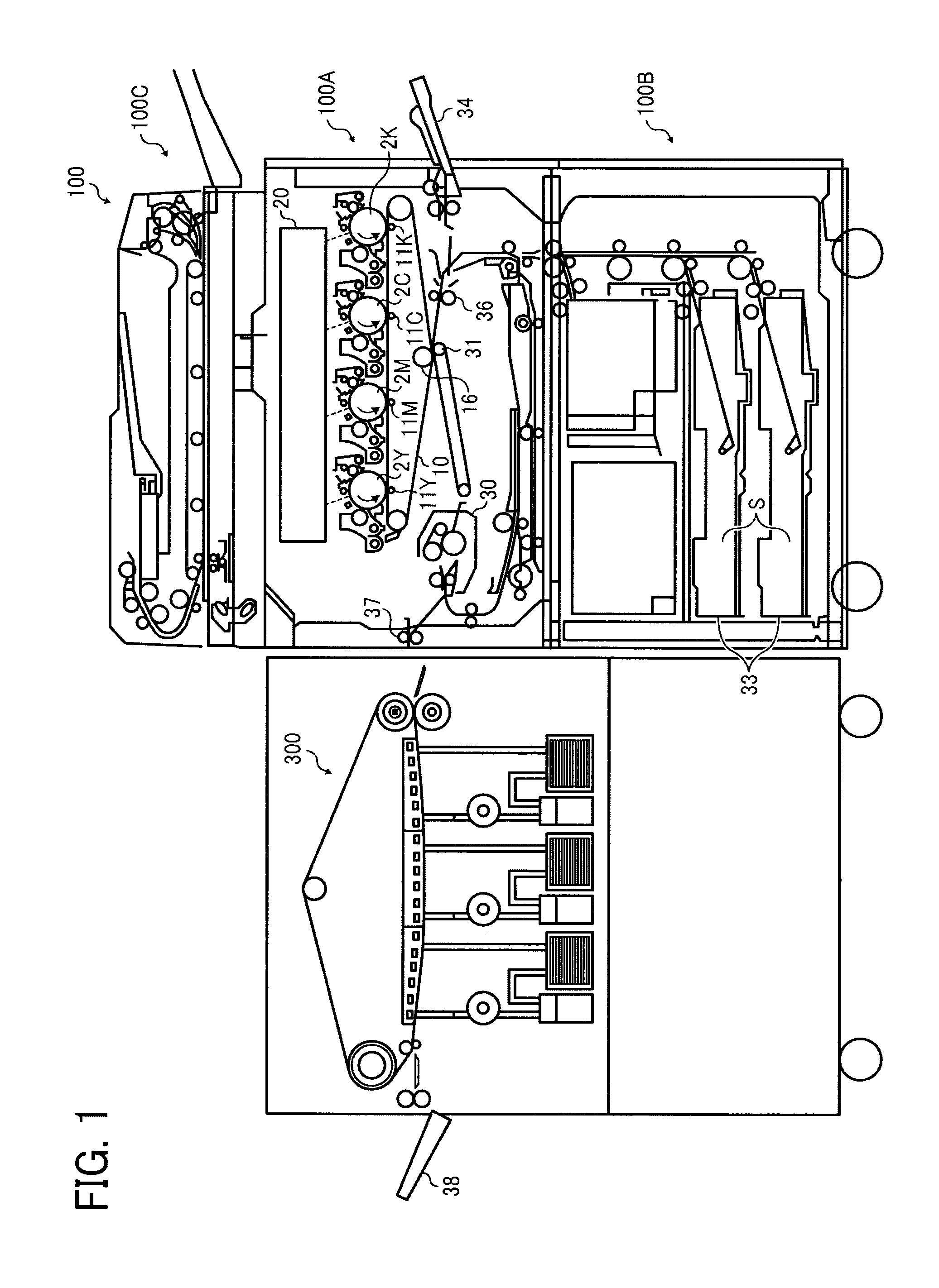
[0031]FIG. 1 schematically illustrates an image forming apparatus 100 according to one embodiment of this patent specification.

[0032]As shown in FIG. 1, the image forming apparatus 100 is a digital color imaging system that can print a color image on a recording medium such as a sheet of paper S according to image data, consisting of a generally upper, printer section 100A, and ...


PUM


Abstract

A glossing device includes a heater member, a stripper member, an endless rotary belt, a pressure member, and a belt cooler. The heater member is subjected to heating. The stripper member is disposed parallel to the heater member. The endless rotary belt is looped for rotation around the heater member and the stripper member in a longitudinal, conveyance direction of the belt. The pressure member is disposed opposite the heater member via the belt. The heater member and the pressure member press against each other via the belt to form a glossing nip therebetween. The recording medium after passage through the nip remains in contact with the belt as the belt moves from the heater member toward the stripper member, and separates from the belt as the belt passes around the stripper member. The belt cooler is disposed adjacent to the belt to cool the belt.

Description

CROSS-REFERENCE TO RELATED APPLICATION[0001]This patent application claims priority pursuant to 35 U.S.C. §119 to Japanese Patent Application No. 2011-138985, filed on Jun. 22, 2011, the entire disclosure of which is hereby incorporated by reference herein.BACKGROUND OF THE INVENTION[0002]1. Technical Field[0003]The present invention relates to a glossing device and an image forming apparatus incorporating the same, and more particularly, to a glossing device that processes a toner image with heat and pressure on a recording medium, and an electrophotographic image forming apparatus, such as a photocopier, facsimile machine, printer, plotter, or multifunctional machine incorporating several of these features, which incorporates such a glossing capability.[0004]2. Background Art[0005]In electrophotographic image forming apparatuses, such as photocopiers, facsimile machines, printers, plotters, or multifunctional machines incorporating several of those imaging functions, an image is f...

Claims


Application Information

Patent Timeline
IPC IPC(8): G03G15/20
CPCG03G15/0189G03G2215/0129G03G2215/00805G03G15/6585G03G15/2021G03G21/206G03G2215/2032
Inventor AMITA, AKIYASUKUNII, HIROYUKIMURAMATSU, SATOSHITOMITA, KUNIHIKO
Owner RICOH KK
Learn More