Decay heat conversion to electricity and related methods
a heat conversion and decay heat technology, applied in nuclear engineering, greenhouse gas reduction, nuclear elements, etc., can solve the problems of inaccessible uhs of the plant, unavoidable decay heat, and a large risk of nuclear waste heat, so as to achieve a lower thermal load
- Summary
- Abstract
- Description
- Claims
- Application Information
AI Technical Summary
Benefits of technology
Problems solved by technology
Method used
Image

Examples
Embodiment Construction
[0002]1. Field of the Invention
[0003]Various embodiments of the present disclosure generally relate to decay heat conversion to electricity and related methods. More specifically, particular embodiments of the present disclosure relate to decay heat conversion to electricity systems and methods for use in, for example, a nuclear reactor.
[0004]2. Description of Related Art
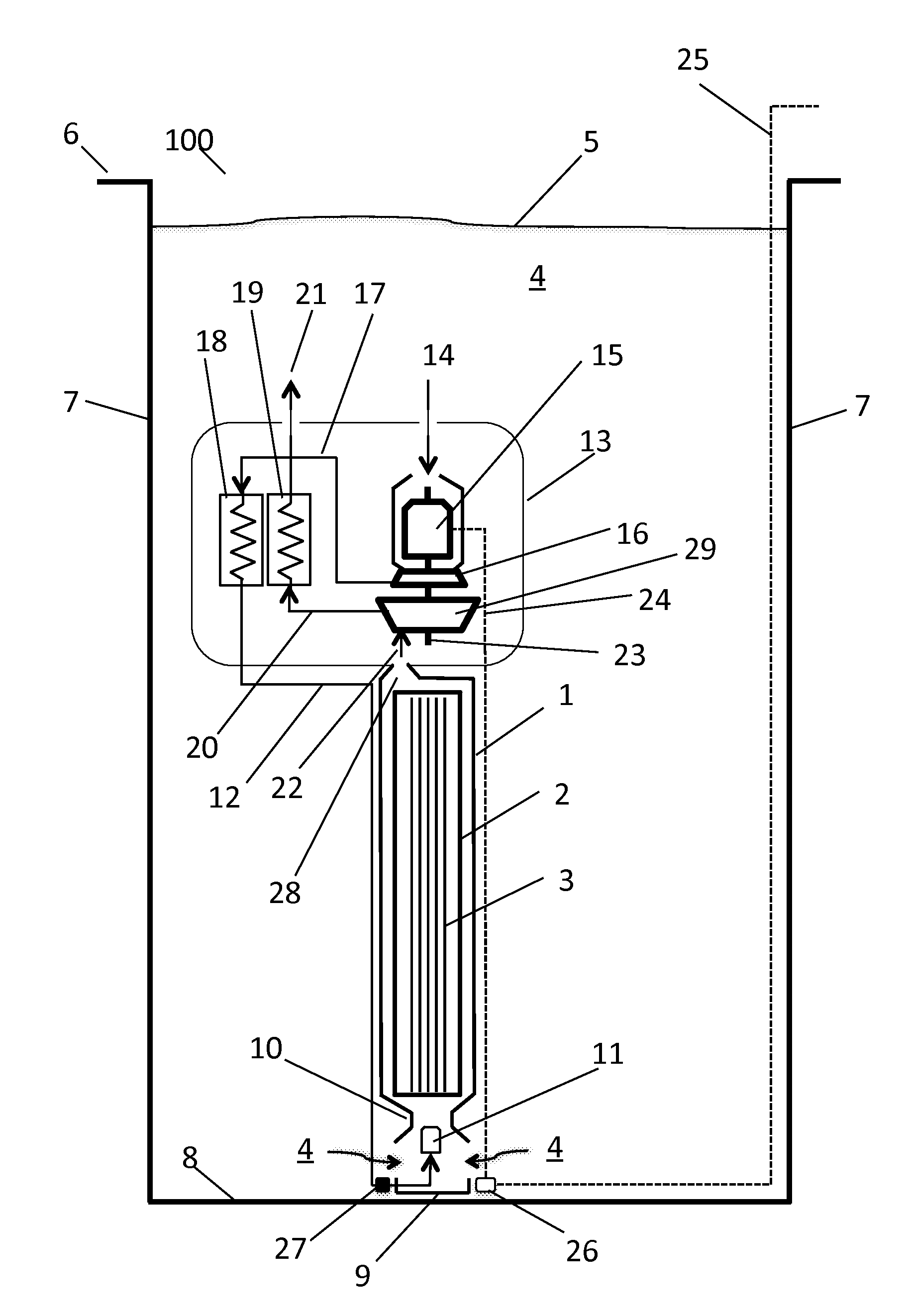
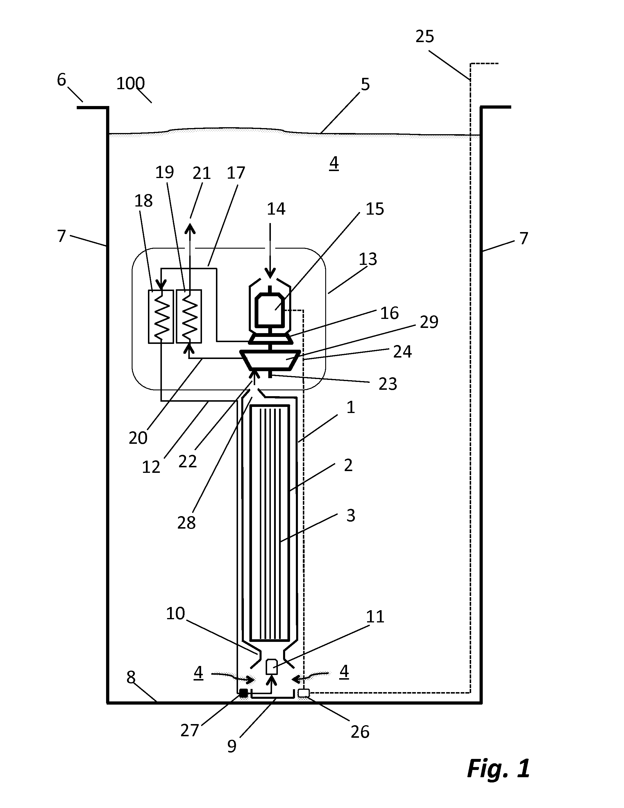
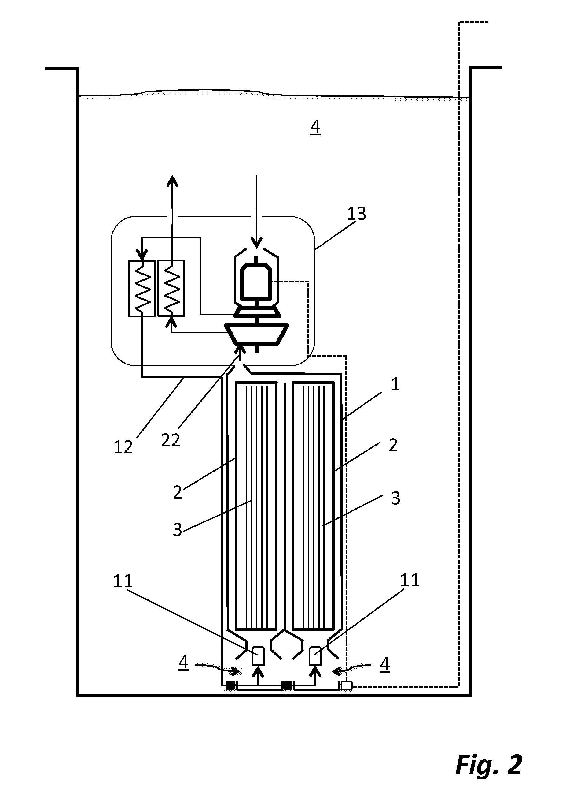
[0005]Nuclear reactors typically rely on active mechanisms for removing decay heat generated from nuclear spent fuel. Decay heat is an unavoidable byproduct of nuclear fission energy, which amounts to approximately 6.5% of the nominal core power at the time of shut-down. Although decay heat is reduced to approximately 0.2% after about a week following a shutdown, decay heat continues to be released from nuclear spent fuel and may pose a significant risk if a proper and continuous cooling mechanism is not provided during shutdown and / or storage in spent or storage fuel pools.
[0006]In general, a spent fuel pool is a r...
PUM
 Abstract
Description
Claims
Application Information
 - R&D
- Intellectual Property
- Life Sciences
- Materials
- Tech Scout
- Unparalleled Data Quality
- Higher Quality Content
- 60% Fewer Hallucinations
Browse by: Latest US Patents, China's latest patents, Technical Efficacy Thesaurus, Application Domain, Technology Topic, Popular Technical Reports.
© 2025 PatSnap. All rights reserved.Legal|Privacy policy|Modern Slavery Act Transparency Statement|Sitemap|About US| Contact US: help@patsnap.com