
Sensor having a sensor housing

a sensor and housing technology, applied in the direction of fluid pressure measurement, instruments, electrical apparatus construction details, etc., can solve the problems of promoting corrosion, affecting the overall sensor, and affecting the sealing of the insert parts, so as to achieve a high level of exhaust gas resistance and simple and short electrical connection

Active Publication Date: 2012-12-20
ROBERT BOSCH GMBH
View PDF6 Cites 1 Cited by
  • Summary
  • Abstract
  • Description
  • Claims
  • Application Information

AI Technical Summary

Benefits of technology

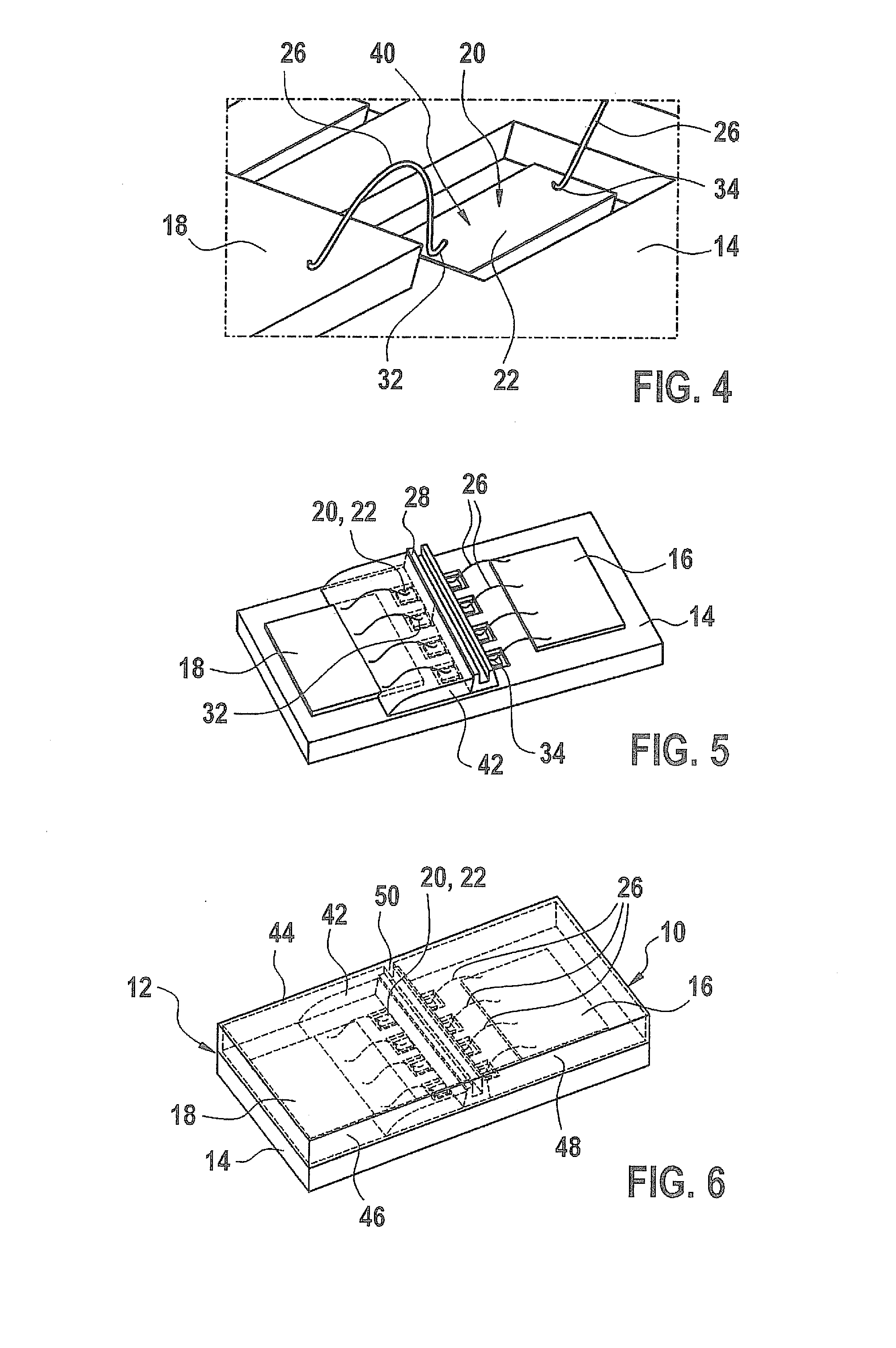
[0010]According to the proposed approach according to the present invention, an electronic component, for example an ASIC or a sensor element, is mounted in a base plate of a sensor housing, which in particular is made of plastic. The electronic component and the sensor element are preferably glued onto an upper plane surface of the base plate which is exposed to the medium. An electrical connection such as a printed conductor, for example, is situated approximately in the middle between the sensor element and the electronic component, for example an ASIC, situated at a distance therefrom. This electrical connection, which is used as a printed conductor, is preferably provided using MID technology, and may, for example, be provided by metal plating which includes a gold layer which covers a base layer such as a nickel underlayer, for example. The metal platings produced with the aid of MID technology are preferably introduced into depressions in the plane surface of the base plate of the sensor housing. In molded interconnect device (MID) technology, conductive patterns in the form of a structured metal layer are applied to three-dimensional injection-molded circuit substrates. Within the scope of MID technology, mechanical and electrical functions are combined in the component; in addition, the housing function and circuit substrate function are combined, and the mechanical connecting and fixing elements and snap-fit hooks are integrated. This results in a significant reduction in the material use and the number of individual parts. Furthermore, the installation effort for the various components may be greatly reduced, and the process chain may be shortened.
[0014]The adhesive material which is applied in the form of an adhesive bead to the metal plating used as a printed conductor is placed between the two bonding sites in such a way that it is reliably ensured that the bonding sites do not contact one another. Consequently, the bonding sites are not subjected to mechanical load, which results in a very robust design of an electrical connection.
[0016]The adhesive material, preferably in the form of an adhesive bead, which is applied to the metal platings used as a printed conductor is media-tight, and also seals off the base plate and cover plate upon joining, so that no medium flows from the chamber for accommodating the sensor element, formed when the cover element and the base plate are joined, into the chamber in which the electronic component, for example an ASIC, is accommodated. The flexibility of the adhesive material of the adhesive bead compensates for dimensional and installation tolerances in a particularly advantageous way.
[0018]A particularly simple and short electrical connection is established between a sensor element and an electronic component, for example an ASIC, as a result of the proposed approach according to the present invention. The simple, short electrical connection offers advantages with regard to electromagnetic compatibility, space requirements, and costs. In addition, with the aid of the proposed approach according to the present invention for media-tight connections between electronic components and the sensor element, a high level of exhaust gas resistance of the overall sensor thus formed may be achieved. Furthermore, a mechanically robust design is advantageously provided by at least two bond connections which lead onto a metal plating which represents a printed conductor. The seal via the adhesive bead is achieved in particular outside the regions of the bonding sites, so that the bonding sites are not subjected to mechanical load.

Problems solved by technology

However, the required media seal-tightness of insert parts is generally not achieved.
In addition, a gold or gold-plated surface of the conductor comb may be attacked due to the bonding process, which promotes the formation of corrosion.

Method used


Image

  • Sensor having a sensor housing
  • Sensor having a sensor housing
  • Sensor having a sensor housing

Examples


Embodiment Construction

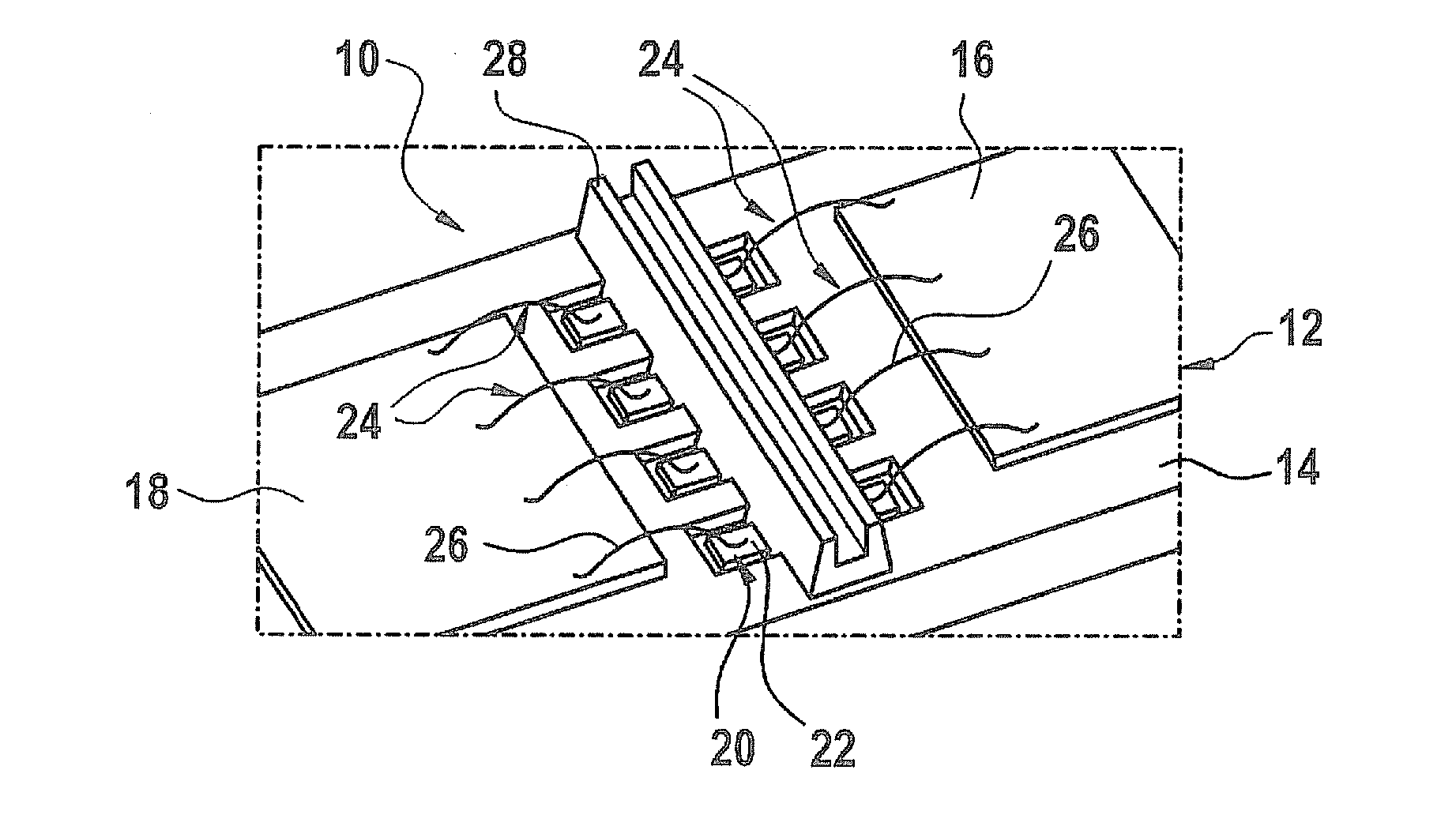
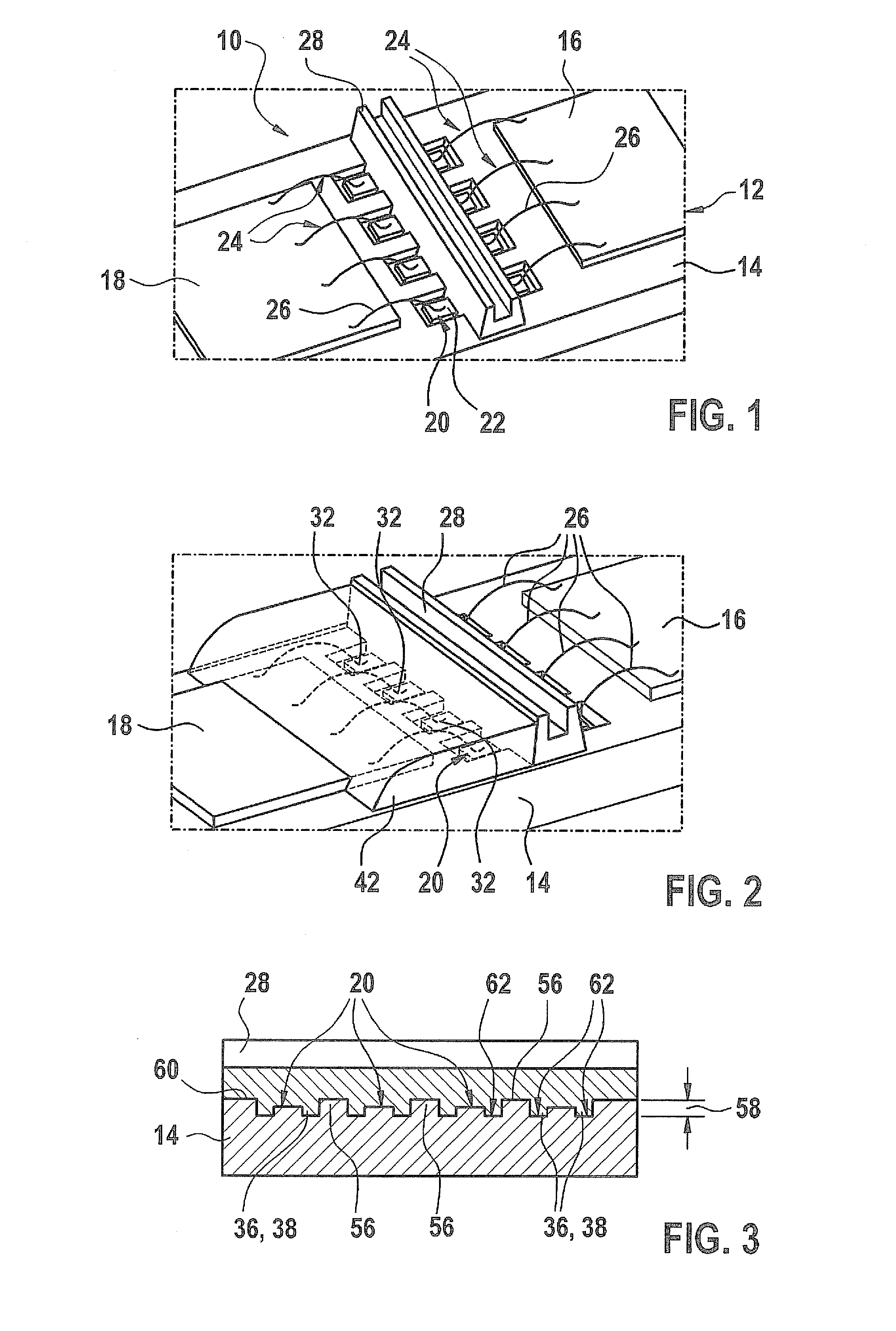
[0025]FIG. 1 shows a base plate of a sensor housing which includes a sensor element and an electronic component, for example an ASIC.

[0026]A sensor 10, which is only schematically illustrated, is a low-pressure sensor, for example; an electronic component 16, for example an ASIC, as well as a sensor element 18 which is exposed to the medium, are situated on a shared base plate 14. Electronic component 16 and sensor element 18 are preferably glued onto a plane surface 60 of base plate 14 of sensor housing 12. As is apparent from the illustration according to FIG. 1, electronic component 16, which may be an ASIC, for example, and sensor element 18 are connected to one another via individual bonding wires 26. Bonding wires 24 contact the oppositely situated ends of a printed conductor 20, which may be provided by a metal plating 22, for example. A spacing is provided between the individual ends of metal platings 22, which are used as a printed conductor 20, and bonding wires 26, in the...


PUM


Abstract

A sensor has a sensor housing, an electronic component, and a sensor element. The electronic component and the sensor element are connected to one another in a media-tight manner. An adhesive which provides a seal is placed between bonding sites of a bonding wire of the at least one electrical connection.

Description

BACKGROUND OF THE INVENTION[0001]1. Field of the Invention[0002]The present invention relates to a sensor having a sensor housing.[0003]2. Description of the Related Art[0004]Published German patent application document DE 102 23 357 A1 relates to a pressure measurement device. The pressure measurement device includes a housing in which a substrate provided with a sensor element and electrical connecting elements is situated. The housing has a first housing chamber which encloses the sensor element and is connected to a first pressure channel of a first pressure connection, and a second housing chamber which is sealed with respect to the first housing chamber and which encloses at least the electrical connecting elements. The housing has a third housing chamber which is sealed with respect to the first housing chamber and the second housing chamber, and which is connected to a second pressure channel of a second pressure connection.[0005]Current developments for pressure sensors pur...

Claims


Application Information

Patent Timeline
IPC IPC(8): H05K7/02H05K13/00
CPCG01L19/14G01L19/148H01L2224/48091H01L2224/48228H05K13/00H01L2224/49175Y10T29/49002H05K7/02H01L2224/48472H01L2924/00H01L2924/00014
Inventor SCHOLZEN, HOLGERGMELIN, CHRISTOPHVOLLERT, JENSELLMER, MARKUS
Owner ROBERT BOSCH GMBH
Learn More