
Apparatus and method for measuring biologic parameters

a technology of biologic parameters and apparatus, applied in the field of apparatus and method for measuring biologic parameters, can solve the problems of preventing the clinical value of measured biologic parameters, unable to provide continuous monitoring for long periods of time, and non-invasive techniques that fail to deliver the clinical usefulness needed, and achieves great visual impact and resolution.

Active Publication Date: 2012-12-13
BRAIN TUNNELGENIX TECH CORP
View PDF2 Cites 57 Cited by
  • Summary
  • Abstract
  • Description
  • Claims
  • Application Information

AI Technical Summary

Benefits of technology

[0333]Another advantage of the present invention is that the heating element does not need to reach high levels of temperature, such as 44 degrees C., since the tunnel area is extremely vascularized and associated with a unique blood vessel which is terminal (which means that the total amount of blood is delivered to the site) in addition to having the thinnest skin interface in the whole body, thereby allowing a lower temperature of a heating element to be used for increasing blood flow to the area. The preferred temperature of the heating element is equal to or less than 44 degrees Celsius, and preferably equal to or less than 41 degrees Celsius, and most preferably equal to or less than 39 degrees Celsius, and even most preferably equal to or less than 38 degrees Celsius.
[0334]The electrochemical sensor of the measuring portion 2006 for blood gas and glucose analysis has the same specialized dimensions and shape described for the other sensors of the invention, in accordance with the present invention and specialized anatomy of the BT and other surrounding tunnels. The device includes a measuring portion 2006 having a sensor, said sensor preferably being an electrochemical or optical sensor, and an associated heating element of specialized dimensions, with said measuring portion 2006 located adjacent to the BT or on the skin at the BT or other described tunnels of the invention. One of the objects of the invention includes providing a device of the described kind to be used at the BT for measurement of the arterial oxygen pressure and other blood gases such as carbon dioxide, carbon monoxide, anesthetic gases, and the like.
[0335]FIG. 2 illustrates a comparison between transcutaneous measurement of the arterial oxygen pressure in the prior art and the present invention. FIG. 2 shows the skin 2270 with its three thick layers, which is present in the whole body. Methods of the prior art use this skin 2270, which has several thick layers, namely subcutaneous tissue (fat tissue) 2272, thick dermis 2274, and thick epidermis 2276. Underneath this thick skin tissue 2270 there are small blood vessels 2278. Oxygen represented by small squares 2280 diffuses through the walls of the small blood vessels 2278, as indicated by the two small arrows in each blood vessel 2278. Contrary to the thick and multilayered skin 2270 present in other parts of the body, which comprised the method used by the prior art, the method and apparatus of the present invention uses specialized skin 2290 at the BT 2282, which has a large vascular bed 2284, no fat issue, a thin dermis 2286, and thin epidermis 2288. A large blood vessel and large vascular bed 2284 present in the brain tunnel provides more stable and more accurate level of molecules and substances such as oxygen level as well as the level of other blood substances such as glucose. Contrary to the method of the prior art which tried to measure substances in areas subject to vasoconstriction and subject to the effect of drugs, the present invention teaches device and methods using a vascular bed 2284 at the brain tunnel that is not subject to such vasoconstriction.
[0336]Skin 2270 of the prior art is thick and has a thick subcutaneous layer 2272 in comparison with the thin skin 2290 of the BT. In the method of the prior art, oxygen molecules 2280 from small blood vessel 2278, which is located deep in the body, have to cross thick layers of skin 21742 (fat tissue), 2174 (dermis), 2176 (epidermis and dead cells) present in said skin 2270 in order for said oxygen molecules 2280 to reach a conventional sensor of the prior art. Accordingly, in the method of the prior art the oxygen 2280 from vessel 2278 has a long path before reaching a sensor of the prior art. Oxygen 2280 diffuses through the wall of the small blood vessel 2278 and through the subcutaneous tissue 2272 to finally reach a thick dermis 2274 and a thick layer of dead cells 2276 at skin 2270, to only then reach conventional sensors of the prior art. As can be seen, the number of oxygen molecules 2280 drop drastically from around vessel 2278 to surface of skin 2271 as it moves along the long path of conventional thick skin 2270 present in the body.
[0337]Contrary to the prior art, the method and device of the present invention uses a specialized and extremely thin skin 2290 of the BT, in which oxygen molecules 2280 from vessel 2284 have an extremely short path to reach specialized sensor 2000 of the present invention. Oxygen molecule 2280 is right underneath the thin skin 2290 since terminal large vascular area 2284 lies just underneath the thin skin 2290, and thus oxygen 2280 rapidly and in an undisturbed fashion reaches specialized sensor 2000. This allows an undisturbed diffusion of oxygen from vessel 2284 to sensor 2000 without any drop of the partial oxygen pressure. Because the specialized skin 2290 of the BT produces a rapid and undisturbed diffusion of oxygen (and other blood gases) to the special sensor 2000 of the present invention and the area measured is characterized by a natural condition of hyperperfusion, the present invention results in more accurate measurement than previously available estimates of partial blood gas pressures.
[0338]An exemplary transcutaneous blood gas sensor of the present invention consists of a combined platinum and silver electrode covered by an oxygen-permeable hydrophobic membrane, with a reservoir of phosphate buffer and potassium chloride trapped inside the electrode. FIG. 2A shows a small heating element 2298, which is located inside the silver anode. Oxygen 2280 diffuses through the skin 2290 and reaches sensor 2292 wherein a reduction of oxygen occurs generating a current that is converted into partial pressure of oxygen. It is understood that other substances can be measured. Exemplarily, carbon dioxide can be measured with the invention, wherein carbon dioxide molecules diffuse across a permeable plastic membrane into the inner compartment of the electrode where the molecule reversibly reacts with a buffer solution altering the pH which produces a measurable signal, said signal corresponding to the amount of the substance or partial pressure of the gas. A processing circuit can be used to calculate the partial pressure of the substance based on predetermined calibration lines.

Problems solved by technology

Interfering constituents and variables can introduce significant source of errors that prevent measured biologic parameters from being of clinical value.
Such techniques have many drawbacks including difficulties in providing continuous monitoring for long periods of time.
Non-invasive techniques also failed to deliver the clinical usefulness needed.
The placement of a sensor on the skin characterized by the presence of interfering constituents do not allow obtaining clinically useful nor accurate signals due to the presence of said interfering constituents and background noise which greatly exceeds the signal related to the physiologic parameter being measured.
Thus measurement of temperature using the skin did not achieve precision nor accuracy because previous techniques used sensors placed on skin characterized by the presence of adipose tissue.
An invasive, artificial, inconvenient, and costly process is currently used to measure internal (core) temperature consisting of inserting a catheter with a temperature sensor in the urinary canal, rectum or esophagus.
But such methodology is not suitable for routine measurement, it is painful, and has potential fatal complications.
Abreu disclosed in U.S. Pat. No. 6,120,460 apparatus and methods for measuring core temperature continuously using a contact lens in the eyelid pocket, but the contact lens is a semi-invasive device which requires prescription by a physician and sometimes it is not easy to place the contact lens in the eye of an infant or even in adults and many people are afraid of touching their eyes.
There are several drawbacks and limitations in the prior art for continuous and / or core measurement of temperature.
To get core temperature nurses invasively place a tube inside the body which can cause infection and costly complications.
Measurement of core temperature on a routine basis in the hospital and / or continuously is very difficult and risky because it requires an invasive procedure with insertion of tubes inside the body or by ingesting a thermometer pill.
The thermometer pill can cause diarrhea, measure temperature of the fluid / food ingested and not body temperature, and have fatal complications if the pill obstructs the pancreas or liver ducts.
Placement of sensors on the skin do not provide clinically useful measurements because of the presence of many interfering constituents including fat tissue.
It is not possible to acquire precise and clinically useful measurements of not only brain temperature, but also metabolic parameters, physical parameters, chemical parameters, and the like by simply placing a sensor on the skin.

Method used


Image

  • Apparatus and method for measuring biologic parameters
  • Apparatus and method for measuring biologic parameters
  • Apparatus and method for measuring biologic parameters

Examples


Embodiment Construction

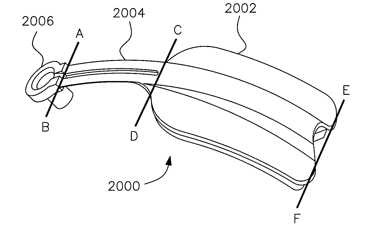
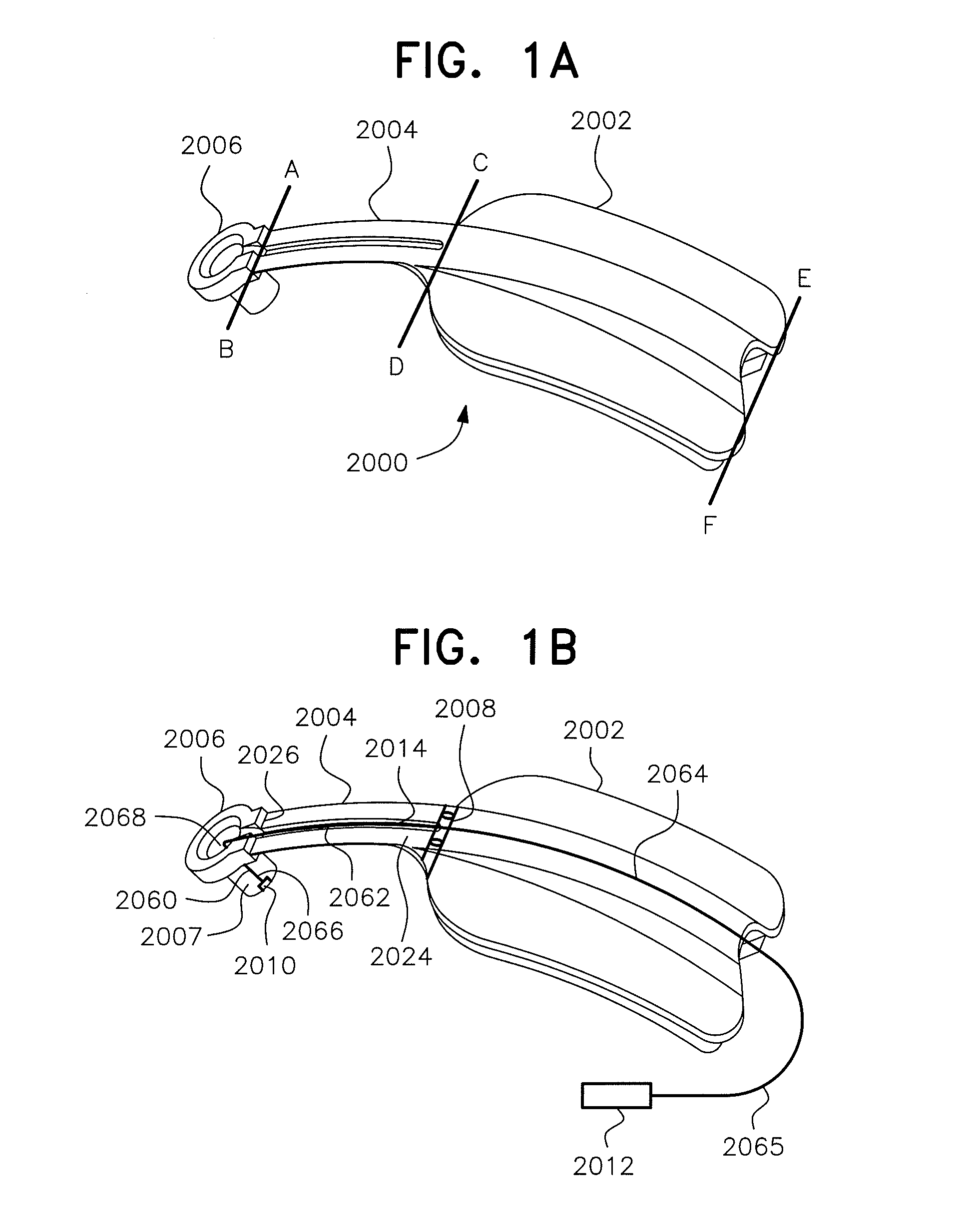
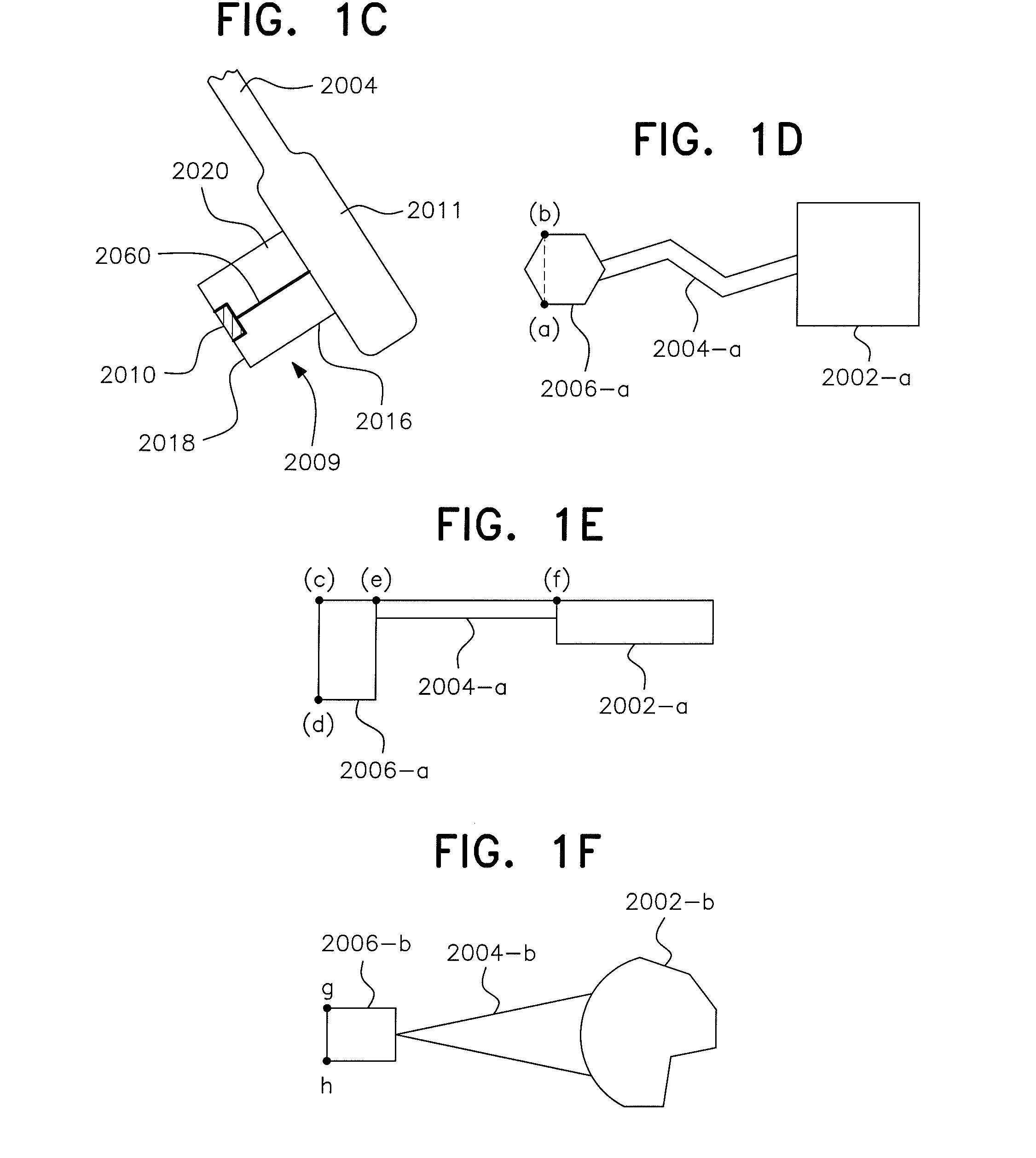
[0232]FIGS. 1A to 1Z show preferred embodiments for the sensing and detecting system of the present invention. It is important to note that due to the specialized anatomic and physical configuration of the Brain Temperature Tunnel (BTT) as described in U.S. patent application Ser. No. 10 / 786,623, hereby incorporated by reference in its entirety, special dimensions and configurations of a sensing device are required, and will be reflected by the specialized dimensions and structure of the present invention disclosed herein. Accordingly, FIG. 1A shows the specialized support structure 2000, referred herein as sensing device 2000 which includes a specialized body 2002, which includes an essentially flexible substrate, an arm 2004, and a sensing portion such as a measuring portion 2006.

[0233]Sensing device 2000, for purposes of illustration, is shown as comprised of three parts, body 2002, arm 2004, and measuring portion 2006. Body 2002 is demarcated by line EF and line CD. Arm 2004 is ...


PUM


Abstract

Support structures for positioning sensors on a physiologic tunnel for measuring physical, chemical and biological parameters of the body and to produce an action according to the measured value of the parameters. The support structure includes a sensor fitted on the support structures using a special geometry for acquiring continuous and undisturbed data on the physiology of the body. Signals are transmitted to a remote station by wireless transmission such as by electromagnetic waves, radio waves, infrared, sound and the like or by being reported locally by audio or visual transmission. The physical and chemical parameters include brain function, metabolic function, hydrodynamic function, hydration status, levels of chemical compounds in the blood, and the like. The support structure includes patches, clips, eyeglasses, head mounted gear and the like, containing passive or active sensors positioned at the end of the tunnel with sensing systems positioned on and accessing a physiologic tunnel.

Description

[0001]This application is a Continuation of U.S. patent application Ser. No. 11 / 585,357, filed on Oct. 24, 2006, which is a complete application of Provisional App. Nos. 60 / 729,232 and 60 / 802,503, filed on Oct. 24, 2005 and May 23, 2006, respectively, herein incorporated in their entirety by reference.FIELD OF THE INVENTION[0002]The present invention includes support and sensing structures positioned in a physiologic tunnel for measuring bodily functions and to manage abnormal conditions indicated by the measurements.BACKGROUND OF THE INVENTION[0003]Interfering constituents and variables can introduce significant source of errors that prevent measured biologic parameters from being of clinical value. In order to bypass said interfering constituents and achieve undisturbed signals, invasive and semi-invasive techniques have been used. Such techniques have many drawbacks including difficulties in providing continuous monitoring for long periods of time. Non-invasive techniques also fa...

Claims


Application Information

Patent Timeline
Patent Type & Authority Applications(United States)
IPC IPC(8): A61B5/01
CPCA61B5/0002A61B5/0008A61B5/01A61B5/6814A61B8/0808A61B5/6887A61B2560/0418A61B5/6821A61B5/6833A61B5/4064A61P7/02A61P9/04Y02A90/10A61B5/00A61B5/6803A61B2562/0271G01K13/20
Inventor ABREU, MARCIO MARC
Owner BRAIN TUNNELGENIX TECH CORP
Learn More