Eureka AIR delivers breakthrough ideas for toughest innovation challenges, trusted by R&D personnel around the world.

Battery transfer apparatus

a technology of battery transfer and battery, which is applied in the direction of vehicle maintenance, transportation items, and refuse collection, etc., can solve the problems of time-consuming and difficult operation of removing batteries from vehicles

Active Publication Date: 2012-12-13
CROWN EQUIP CORP
View PDF8 Cites 15 Cited by
  • Summary
  • Abstract
  • Description
  • Claims
  • Application Information

AI Technical Summary

Benefits of technology

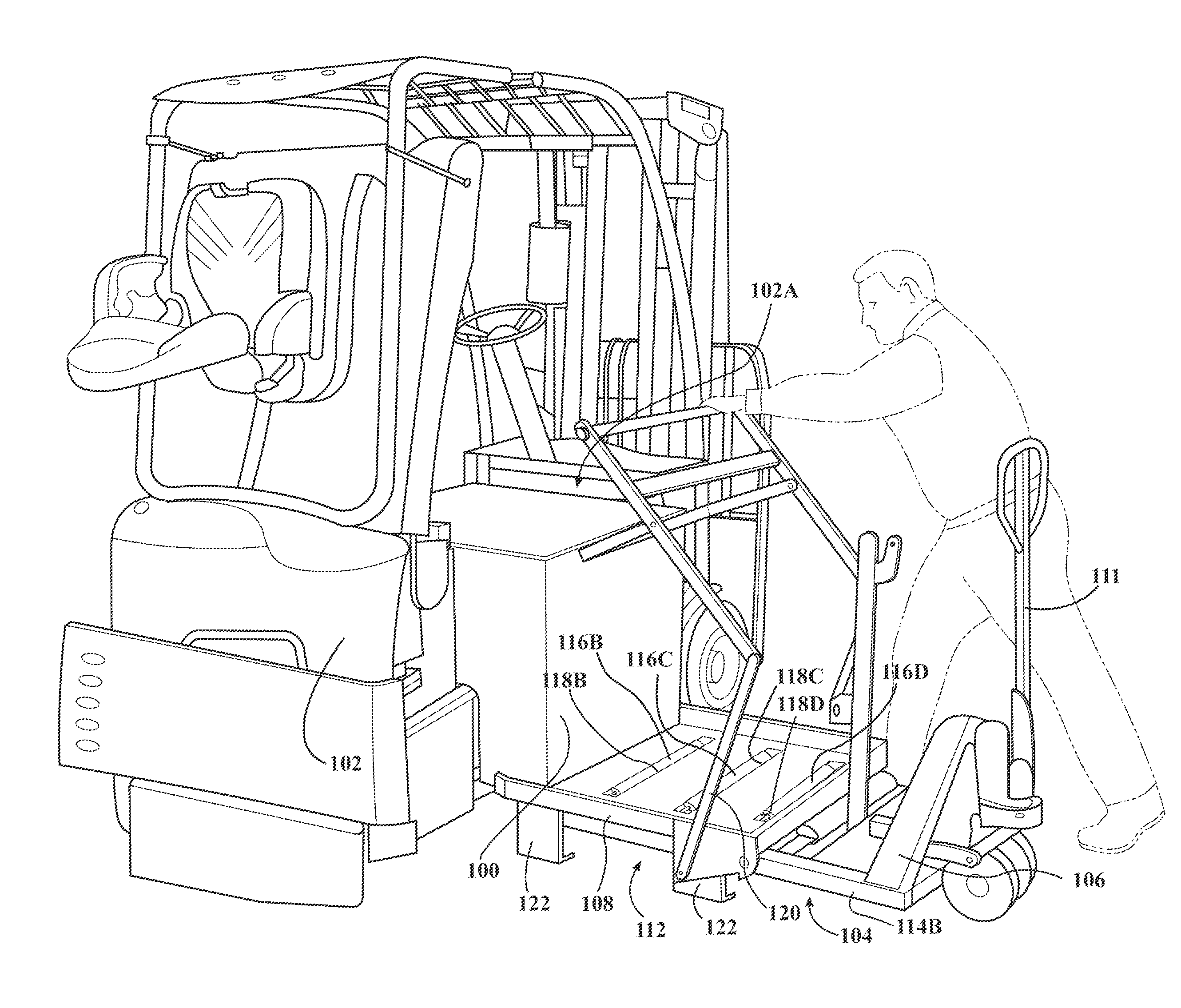
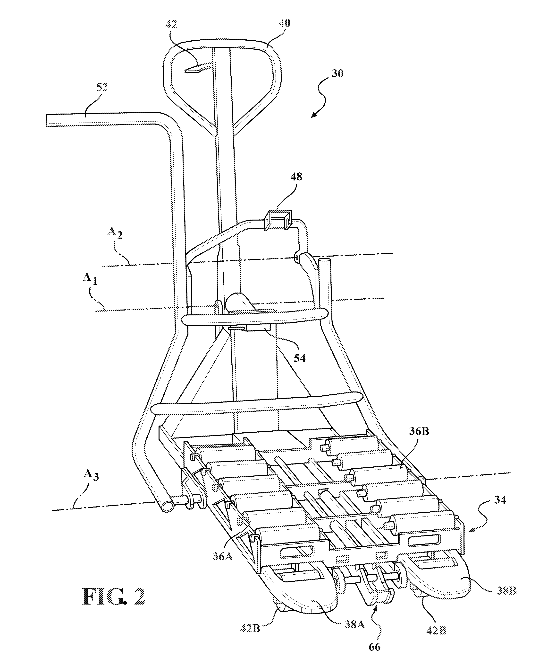
[0006]In accordance with a second aspect of the present invention, a system is provided for loading and / or unloading batteries from materials handling vehicles. The system comprises a materials handling vehicle comprising a battery compartment, a battery to be loaded into or unloaded from the battery compartment, and a battery transfer apparatus. The battery transfer apparatus comprises a mobile unit for transporting the battery and a battery stand. The mobile unit comprises load handling structure for temporarily supporting the battery, the load handling structure comprising at least one roller that is used to roll the battery into or out of the materials handling vehicle. The battery stand comprises a top wall and support structure, the top wall including at least one opening and the support structure adapted to engage a surface upon which the battery stand is placed so as to support the battery stand on the surface. The battery stand is adapted to be engaged by the mobile unit during a transfer of the battery into or out of the materials handling vehicle by inserting the at least one roller up through the at least one opening in the top wall of the battery stand such that the at least one roller can engage the battery through the at least one opening. The battery stand is capable of storing the battery while the battery is out of the materials handling vehicle when the battery stand is disengaged from the load handling structure.

Problems solved by technology

As batteries that power materials handling vehicle are large and heavy, extracting the batteries from the vehicles can be a difficult and time consuming operation.

Method used


Image

  • Battery transfer apparatus
  • Battery transfer apparatus
  • Battery transfer apparatus

Examples


Embodiment Construction

[0020]In the following detailed description of the preferred embodiments, reference is made to the accompanying drawings that form a part hereof, and in which is shown by way of illustration, and not by way of limitation, specific preferred embodiments in which the invention may be practiced. It is to be understood that other embodiments may be utilized and that changes may be made without departing from the spirit and scope of the present invention.

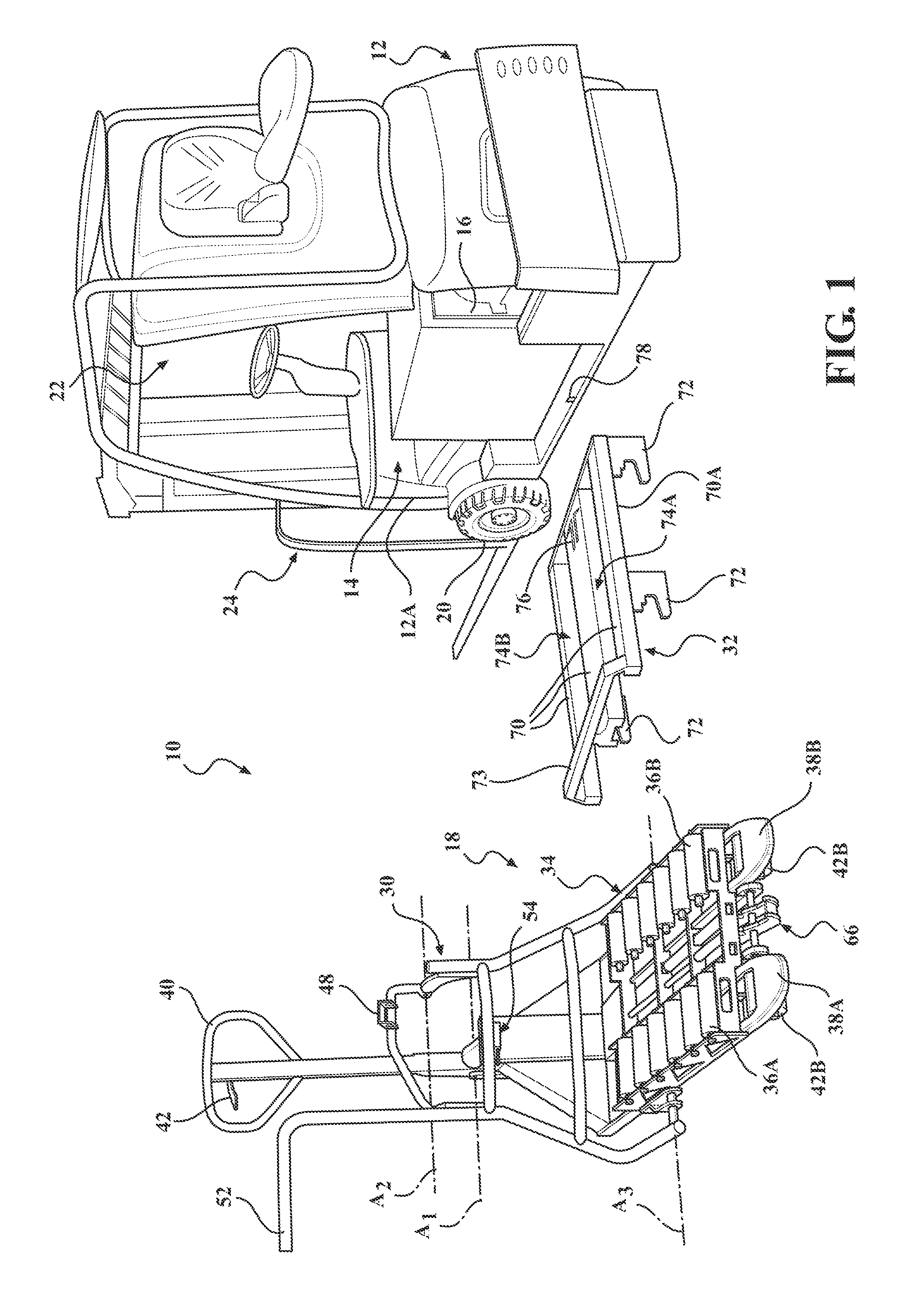
[0021]FIG. 1 illustrates a system 10 used for loading and / or unloading batteries from materials handling vehicles. The system 10 comprises a materials handling vehicle (MHV) 12 having a battery compartment 14, a rechargeable battery 16 to be loaded into and / or unloaded from the battery compartment 14, and a battery transfer apparatus 18. The battery compartment 14 in the embodiment shown is accessible from a side 12A of the MHV 12 and houses the battery 16. The battery compartment 14 comprises conventional rollers (not shown) for rolling...


PUM


Abstract

A battery transfer apparatus for loading / unloading batteries from materials handling vehicles includes a mobile unit and a battery stand. The mobile unit is used to transport batteries into / out of materials handling vehicles and includes load handling structure comprising at least one roller, which is used to roll batteries into / out of materials handling vehicles. A top wall of the battery stand includes at least one opening and support structure of the battery stand engages a surface so as to support the battery stand thereon. The battery stand is engaged by the mobile unit during battery transfer operations by inserting the roller(s) up through the opening(s) in the top wall of the battery stand such that the roller(s) can engage the battery through the opening(s). The battery stand is capable of storing the battery while the battery is out of the materials handling vehicle.

Description

CROSS REFERENCE TO RELATED APPLICATIONS[0001]This application claims the benefit of U.S. Provisional Patent Application Ser. No. 61 / 494,012, filed Jun. 7, 2011, entitled “BATTERY TRANSFER APPARATUS,” the entire disclosure of which is hereby incorporated by reference herein.FIELD OF THE INVENTION[0002]The present invention relates to a battery transfer apparatus for loading and unloading batteries from materials handling vehicles.BACKGROUND OF THE INVENTION[0003]Many types of materials handling vehicles, such as forklift trucks, are powered by rechargeable batteries. When the charge on a battery that is used to power a materials handling vehicle is low or depleted, the battery is typically extracted from the vehicle and replaced by a charged battery. The low / depleted battery is then transported to and recharged at a recharging station, rather than recharging the battery while on board the vehicle, as recharging the battery while on board the vehicle requires the vehicle to be out of ...

Claims


Application Information

Patent Timeline
IPC IPC(8): B65G65/00B60P1/52
CPCB66F9/0754B60L53/80B62B2203/74Y02T10/70Y02T10/7072B60S5/06B66F9/075
Inventor GILLAND, JESS D.OTTO, MATTHEW J.REKOW, CRAIG J.SOLLMANN, CHAD T.TOPP, GARY L.
Owner CROWN EQUIP CORP
Why Eureka
Eureka Blog
Learn More