
Methods for laser cooling of fluorescent materials

a fluorescent material and laser cooling technology, applied in the field of light-matter interaction, to achieve the effects of reducing temperature, reducing radiation, and improving the cooling cycl

Inactive Publication Date: 2012-12-13
CORP DE LECOLE POLYTECHNIQUE DE MONTREAL
View PDF2 Cites 7 Cited by
  • Summary
  • Abstract
  • Description
  • Claims
  • Application Information

AI Technical Summary

Benefits of technology

[0025]Advantageously, the above laser cooling method provides, due in part to the high radiative relaxation rate of the superradiant pulses, an improved anti-Stokes cooling cycle that is more efficient and capable of reaching lower temperatures than traditional cooling cycles based on incoherent anti-Stokes fluorescence.
[0026]Moreover, in embodiments wherein the fluorescent material is a rare-earth-doped host material, the laser cooling method relaxes the constraints on the use of low-phonon-energy materials as host materials by allowing the use of materials having higher phonon energy, which have been thus far considered unsuitable as rare-earth-doped hosts for traditional laser cooling applications.
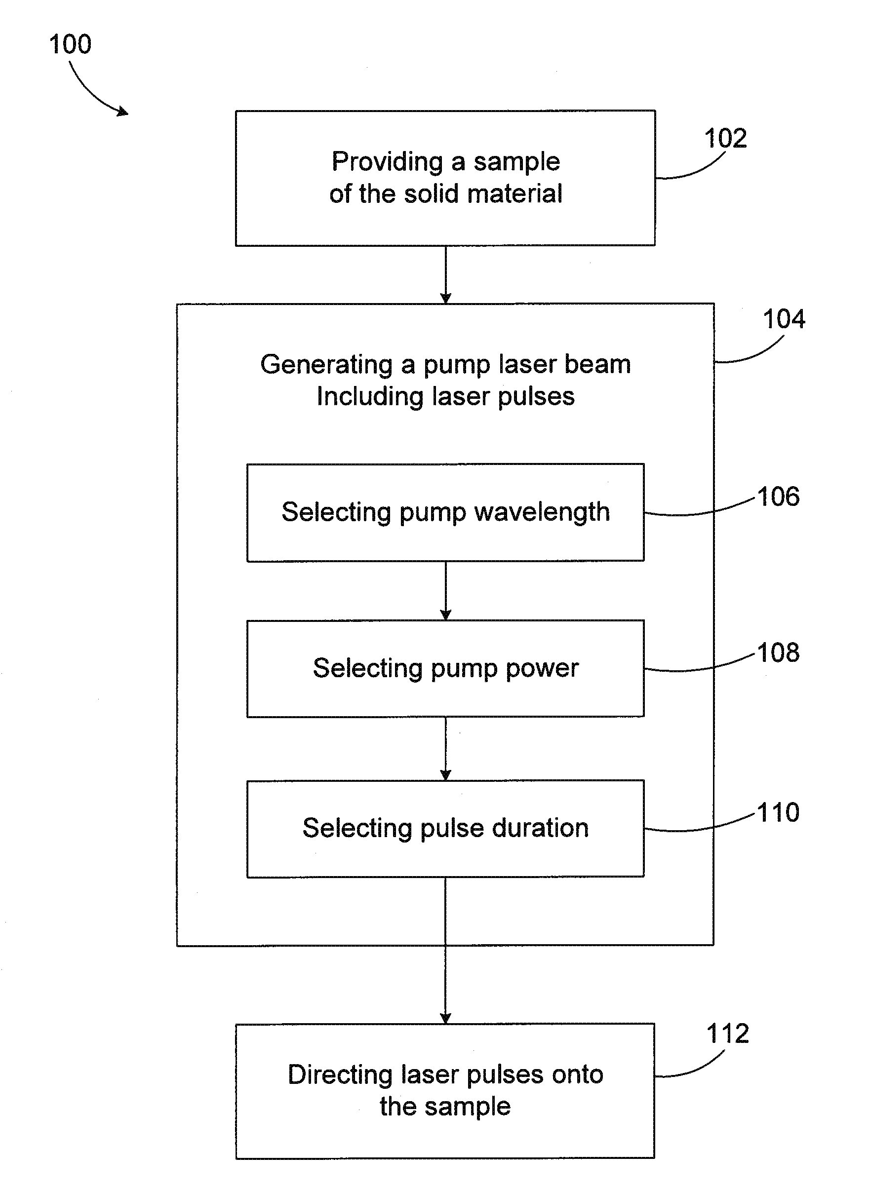
[0027]Further advantageously, contrary to previous known methods employing superradiance to intensify laser cooling of solids in the anti-Stokes regime, the laser cooling method above may be realized by using a single pulsed pump laser beam at a pump wavelength longer than a mean fluorescence wavelength of the solid material to be cooled. Indeed, in methods known in the art, both a CW and a pulsed pump laser sources are employed, whereby the latter generate phonons that heat the material, thus reducing the efficiency of the cooling cycle. The above method helps circumventing this problem.
[0033]Advantageously, by combining a traditional anti-Stokes cooling cycle and an upconversion cooling cycle, the method according to this aspect of the invention helps overcoming the self-termination effects that may be present in either of the two cooling cycles when used on its own.

Problems solved by technology

Moreover, in embodiments wherein the fluorescent material is a rare-earth-doped host material, the laser cooling method relaxes the constraints on the use of low-phonon-energy materials as host materials by allowing the use of materials having higher phonon energy, which have been thus far considered unsuitable as rare-earth-doped hosts for traditional laser cooling applications.

Method used


Image

  • Methods for laser cooling of fluorescent materials
  • Methods for laser cooling of fluorescent materials
  • Methods for laser cooling of fluorescent materials

Examples


Embodiment Construction

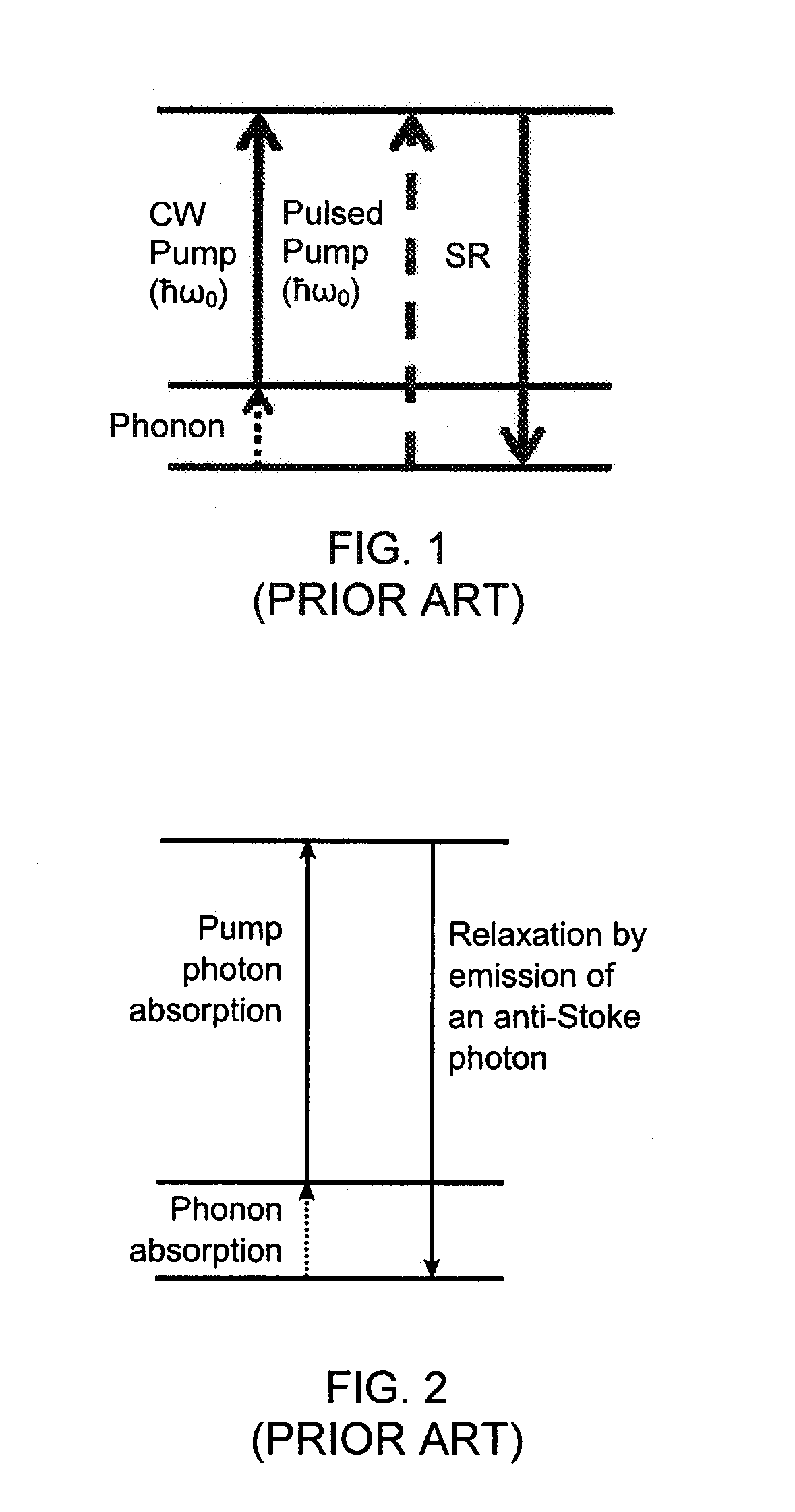
[0052]The present invention generally relates to methods for cooling a fluorescent material with laser radiation. As known in the art, laser cooling of materials, also referred to as optical refrigeration, optical cooling or anti-Stokes fluorescence, may occur in a fluorescent material that absorbs pumping laser radiation at one wavelength and subsequently emits fluorescent radiation that has an average wavelength shorter than that of the pumping laser radiation.

[0053]It is known in the art that an electron may be excited by a photon having an energy corresponding to a difference in energy between two atomic levels. Moreover, it is also known that phonons—quanta of vibrational energy that generates heat—may also be part of the excitation process of an electron by being absorbed thereby, along with a pump photon, in order to provide the appropriate energy for promoting the electron to an upper atomic level. Accordingly, when the excited electron relaxes in a radiative way, the emitte...


PUM


Abstract

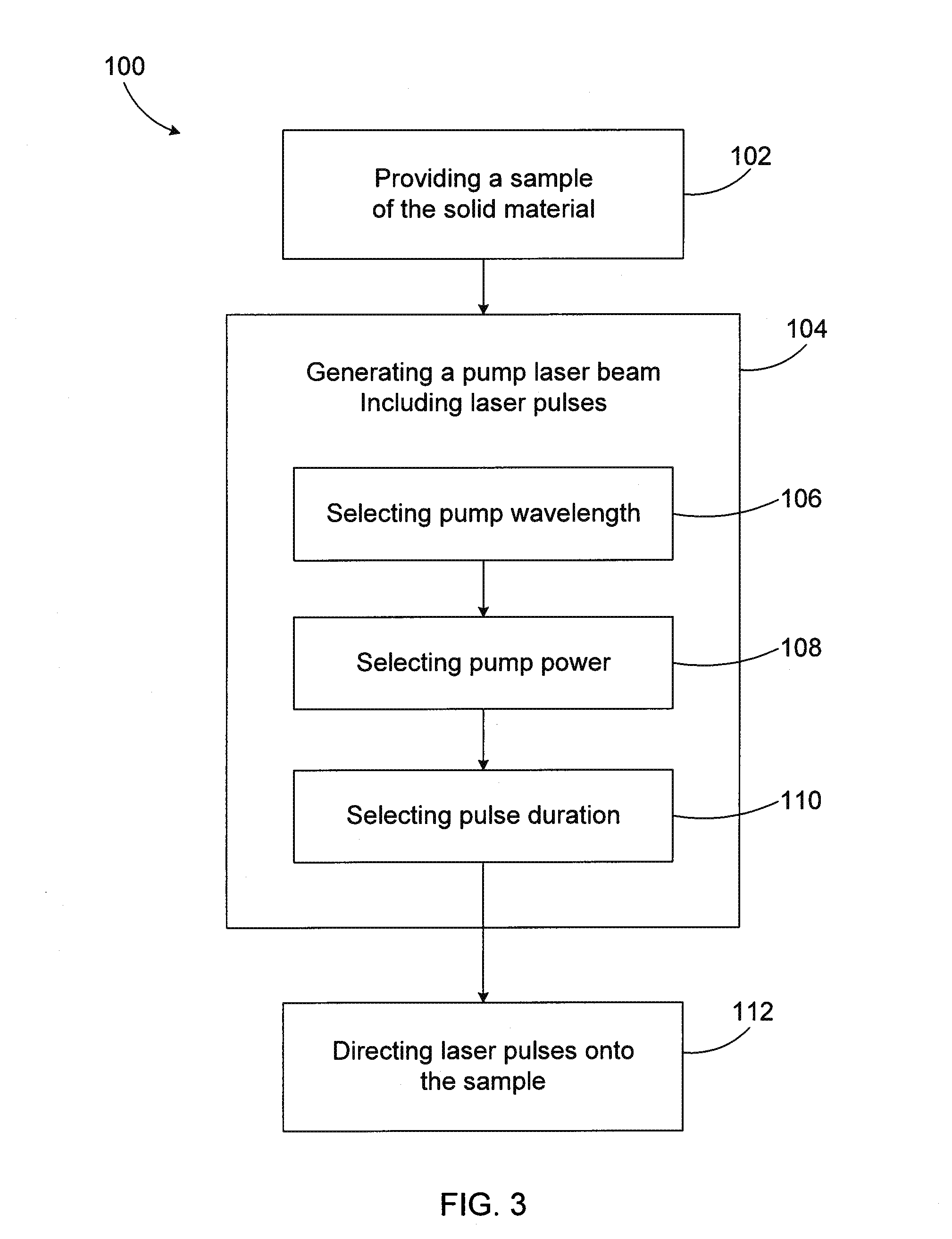
Methods for cooling fluorescent material are provided. A first method includes providing a sample of the material having an elongated direction of light propagation, exhibiting fluorescence at a mean fluorescence wavelength and capable of emitting superradiant pulses with a formation delay time. The method then involves generating a pump pulsed laser beam having a wavelength longer than the mean fluorescence wavelength, a pump power at which superradiant pulses are emitted and a pulse duration shorter than the formation delay time. The pulses are directed onto the sample along the direction of light propagation to produce the superradiant pulses in an anti-Stokes process inducing a cooling of the sample. A second laser cooling method includes a combination of a traditional anti-Stokes cooling cycle and an upconversion cooling cycle, wherein the two cooling cycles act cooperatively to cool the sample.

Description

FIELD OF THE INVENTION[0001]The present invention relates to the field of light-matter interaction, and more particularly concerns laser cooling methods.BACKGROUND OF THE INVENTION[0002]Laser cooling of solids, also referred to as optical refrigeration, optical cooling or anti-Stokes fluorescence cooling, is a fast-developing area in the field of optical science and laser physics. Apart from being of fundamental scientific interest, this topic addresses the relevant technological problem of designing and constructing laser-pumped optical coolers.[0003]The idea of cooling solids by anti-Stokes fluorescence was proposed by Peter is Pringsheim in 1929 [see P. Pringsheim, Z. Phys. vol. 57, p. 739, (1929)]. It has been shown that in some materials, excited atoms emit light having wavelength shorter than that of the light illuminating the material, and that the excess energy is supplemented via thermal (phonon) interactions with the excited atoms [see R. W. Wood, Phil. Mag. Vol. 6, p. 310...

Claims


Application Information

Patent Timeline
IPC IPC(8): F25B21/00
CPCF25B23/00
Inventor KASHYAP, RAMANNEMOVA, GALINA
Owner CORP DE LECOLE POLYTECHNIQUE DE MONTREAL
Learn More