
Reinforced biocompatible ceramic implant and manufacturing method thereof

a biocompatible ceramic and implant technology, applied in the field of bone implants, can solve the problems of major morbidity, risk of morbidity, and conservation challenges, and achieve the effects of improving the mechanical avoiding distortion and embrittlement, and improving the strength of ceramic cranial implants

Active Publication Date: 2012-12-06
S A S 3DCERAM SINTO
View PDF1 Cites 24 Cited by
  • Summary
  • Abstract
  • Description
  • Claims
  • Application Information

AI Technical Summary

Benefits of technology

[0012]The aim of the present invention is therefore to improve the mechanical strength of the ceramic cranial implants so as to avoid the distortion and embrittlement of the implants during their manufacture. The aim of the invention is also to improve the strength of ceramic cranial implants and to enable the manufacture of large size ceramic cranial implants.
[0014]The presence of the one or more reinforcing members allows improving the mechanical strength of the implant during all the manufacturing steps of the workpiece. In particular, they can prevent distortion during debinding and sintering as well as the occurrence of embrittlement areas, such as microcracks in the implant.
[0018]This design is advantageous compared to a design consisting of one or more reinforcing members laid and fixed on the body of the implant after the manufacture thereof. Besides the time savings provided by this design, the risk of poor fixation and / or disbonding of the one or more reinforcing members is also avoided, while increasing their reinforcement capacity.
[0020]Thus, pressure on the underlying anatomical structures is avoided, and especially on the outer face of the dura mater of the brain of the mammal or human destined to receive the implant.
[0028]It has indeed been noticed that, during integration of the implant within the bone tissue, the bone cells did not penetrate the entire thickness of the implant body. It is therefore advantageous to provide the porous areas only in the vicinity of the surface of the implant body, and to provide a non-porous structure at the core of the implant body which reinforces the strength of the implant.
[0029]The one or more reinforcing members are preferably non-porous, which increases their ability to mechanically reinforce the workpiece.

Problems solved by technology

Treatment of bone defects of the skull is now a major problem in maxillofacial surgery and in neurosurgery.
This solution is not without drawback: it presents risks of morbidity at the donor site; the material is only available in limited quantity and is subject to conservation challenges.
However, these implants often lack biocompatibility, and have a low osteoconductivity, which diminishes their integration ability within the existing bone tissue.
However, one of the drawbacks of ceramic implants is their fragility both during the manufacturing process and on the finished workpiece.
These implants are thus subjected to large internal stresses which exert in particular during the heat treatments to which the workpiece is submitted during its manufacture: debinding and sintering.
They therefore lead to a distortion of the implant, which may render it unusable, since unsuited to the shape of the bone defect.
They can also cause the occurence of areas of fragility of the implant likely to promote its rupture.
These drawbacks make it difficult or even impossible to manufacture large size ceramic implants, which limits the use of this material to the repair of small size bone defects.

Method used


Image

  • Reinforced biocompatible ceramic implant and manufacturing method thereof
  • Reinforced biocompatible ceramic implant and manufacturing method thereof
  • Reinforced biocompatible ceramic implant and manufacturing method thereof

Examples


Embodiment Construction

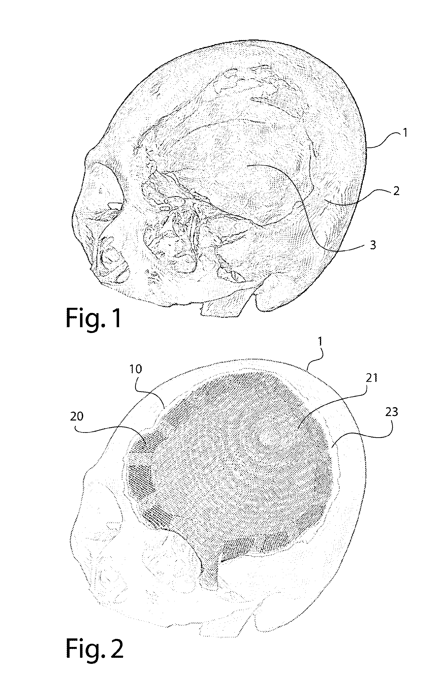
[0049]In reference to FIG. 1, a skull 1 is shown in a perspective view. This skull has a very large cranial defect 2. The cranial defect 2 assumes the shape of a cap that covers a very large part of the frontal bone and part of the parietal bone on the left side and at the center of the skull. The defect extends frontally to the edge of the left orbit of the skull and comprises a tongue-shaped part going past the cap and going down on the left side of the left orbit. The cranial defect reveals the dura mater 3, upper membrane of the meninges, which in particular has for role to protect the brain.

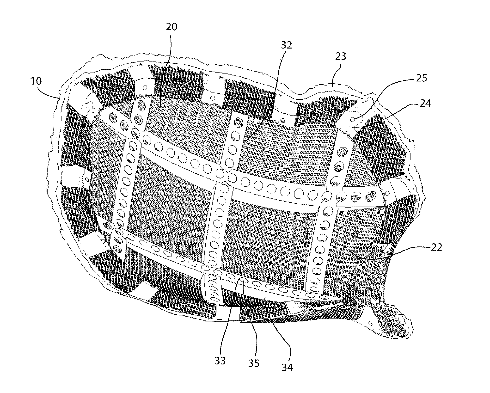
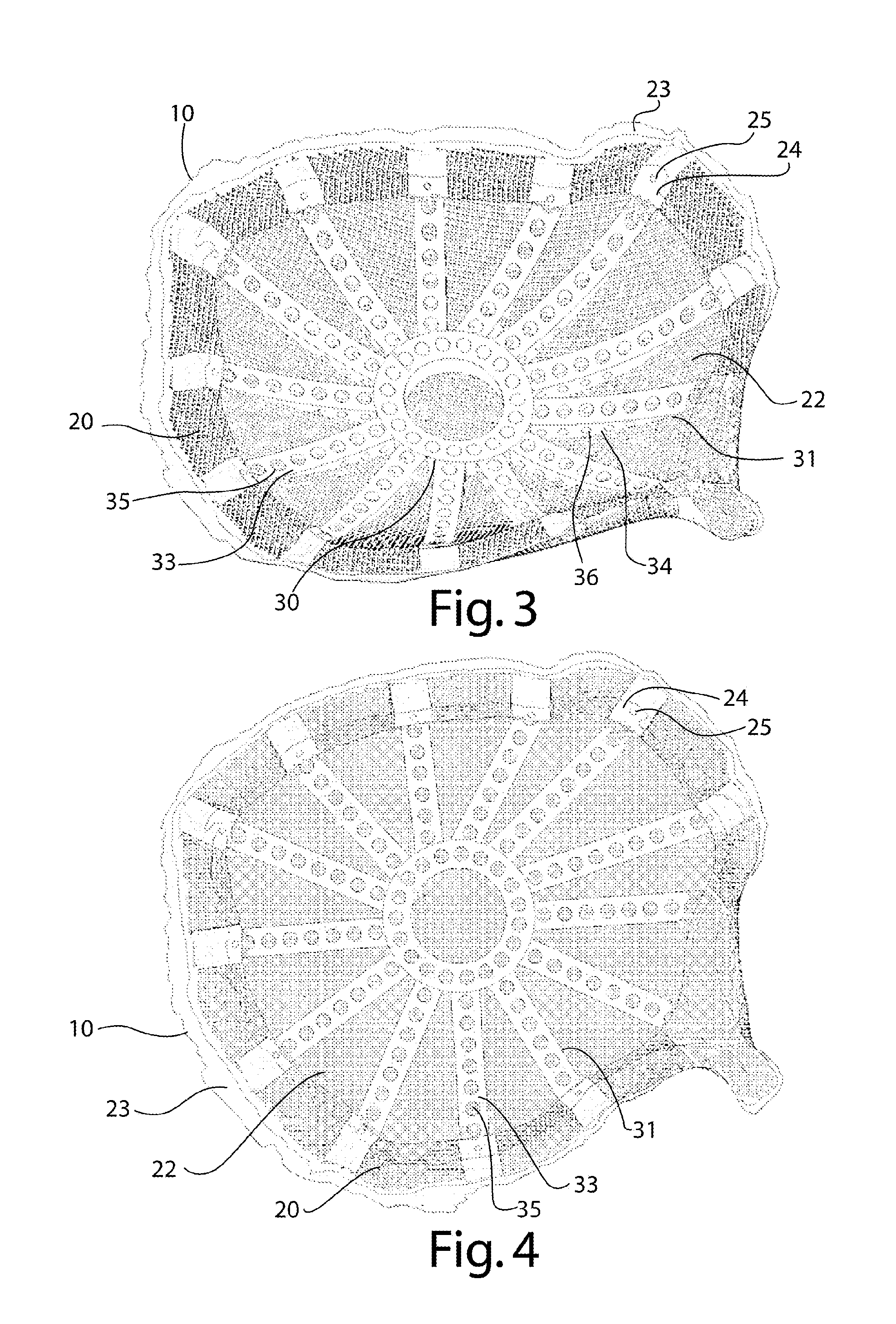
[0050]FIG. 2 shows the skull of FIG. 1 bearing a cranial implant 10 according to a first embodiment of the invention. This implant comprises an implant body 20 which comprises an outer face 21 facing outside the skull and an inner face, not visible in FIG. 2 and facing inside the skull. The shape of the implant substantially reproduces the shape of the cranial defect. The implant therefore h...


PUM


Abstract

A cranial implant designed to fill a cranial defect of the skull of a mammal or a human, wherein the cranial implant is made of biocompatible ceramic and includes an implant body having a shape and size substantially matching the shape and size of the cranial defect to be filled, wherein the implant body includes an outer face facing outside the skull and an inner face facing inside the skull when the implant disposed on the skull, characterized in that the implant includes one or more reinforcing members protruding from the inner face of the implant body. A method of manufacturing the cranial implant is also described.

Description

CROSS REFERENCE TO RELATED APPLICATIONS[0001]Applicant claims priority under 35 U.S.C. 119 of French patent application no. 1154724 filed on May 30, 2011.BACKGROUND OF THE INVENTION[0002]The present invention relates to the field of bone implants, particularly to cranial implants designed to fill a bone defect in the skull of a human or a mammal.[0003]Treatment of bone defects of the skull is now a major problem in maxillofacial surgery and in neurosurgery. The cranial defects may have various origins and occur especially following a developmental anomaly, a bone disease or trauma that resulted in fractures of the skull. They may also be the consequence of a neurosurgical procedure, such as a decompressive craniectomy performed in the case of post-traumatic cerebral edema, or a surgery of extraction of a brain tumor.[0004]These bone defects are repaired during a reconstructive skull surgery, called cranioplasty, during which a bone implant destined to fill the bone defect is inserte...

Claims


Application Information

Patent Timeline
Patent Type & Authority Applications(United States)
IPC IPC(8): A61F2/28G06F17/50
CPCA61B17/842A61L2430/02A61F2/30942A61F2002/30011A61F2002/30878A61F2002/3092A61F2002/30948A61F2002/30952A61F2002/30962A61F2310/00179A61F2310/00203A61F2310/00293A61L27/12A61L27/56A61F2/2875B33Y80/00
Inventor CHAPUT, CHRISTOPHEGAIGNON, RICHARDBRIE, JOEL
Owner S A S 3DCERAM SINTO
Learn More