
Engine simulator for wind tunnel models, method for manufacturing a heater coating on a flow-type body and use of a coating with a conductivity additive on a flow-type body

Inactive Publication Date: 2012-12-06
AIRBUS OPERATIONS GMBH
View PDF14 Cites 0 Cited by
  • Summary
  • Abstract
  • Description
  • Claims
  • Application Information

AI Technical Summary

Benefits of technology

[0008]In an advantageous embodiment, at least one of the two electrodes is designed as a metal band. The metal band may consist of the softest possible, easily bendable and readily conductive metal, with especially copper or aluminum being possible, wherein a tin coating can also be applied to the metal band as an option. Such a metal band can be applied to, on or under the coating, flexibly contacting the flow-type body. Because it is readily moldable, an electrode designed as a metal strip can be adjusted to the shape of the end of the flow-type body, and would thus have the least possible influence on the flow in the region of the end, for example as the result of a bump or the like. For purposes of attachment to the flow-type body, the metal band could exhibit an adhesive film on the lower side, which upon removal of a protective layer makes it possible to securely bond the metal band to the flow-type body.
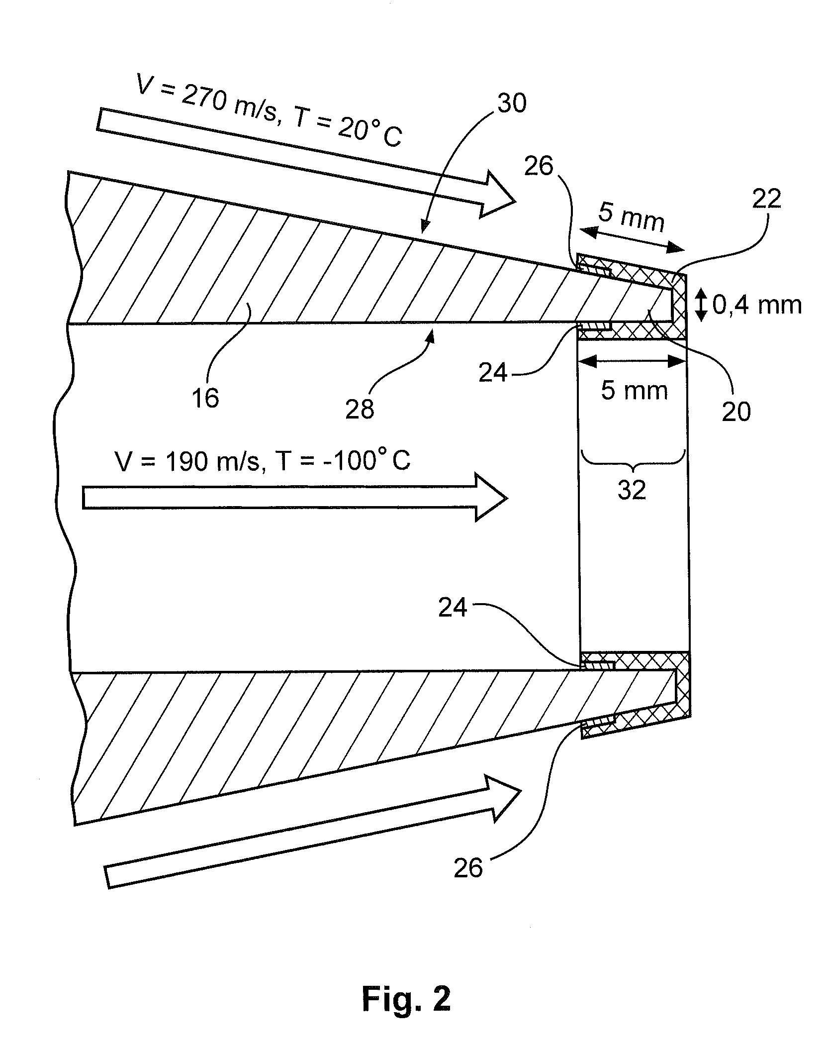
[0010]In another embodiment of the invention, the flow-type body is designed as an outlet nozzle for a central stream from the turbine, and the heater coating extends from an interior side of the flow-type body over the downstream end to an exterior side of the flow-type body. As a result, the coating may reliably heat a relatively large surface area at one end of a flow-type body, thereby reliably preventing ice formation.
[0012]Another embodiment of the invention, the electrodes are annularly arranged on the heater coating, essentially parallel to the surface area of the flow-type body. The surface area here refers to the local surface exposed to the action of the heater coating. A first electrode is here preferably applied flatly to the interior side of the flow-type body, while a second electrode is applied flatly to the exterior side of the flow-type body. The heater coating here likewise extends from the exterior side to the interior side of the flow-type body, and in so doing envelops the two electrodes. This arrangement is especially well suited for equipping a flow-type body shaped like an outlet nozzle. As a result, the configuration consisting of a heater coating and electrodes can be rather flat, while a comparatively large surface area is simultaneously used for applying a voltage. Further, the distance between the two electrodes is very short, so that a moderate level of applied voltage can be selected. Exposing a large area of the trailing edge to be heated yields a uniform flow of current, and hence a uniform heating over the entire circumference of the flow-type body, without gaps coming about. In addition, applying the heater coating with the electrodes arranged on the inside and outside is very easy, since this makes it possible to simply immerse the trailing edge of the flow-type body fitted with the electrodes into a liquid matrix material.
[0018]Furthermore the use of a coating comprised of a matrix material with a conductivity additive as the heater coating to prevent ice formation on a flow-type body of a wind tunnel model is provided.

Problems solved by technology

Such heating films known from prior art may also exhibit a limited mechanical flexibility, and hence a very limited dimensional adjustability, so that they cannot be entirely draped around a trailing edge of a flow-type body.

Method used


Image

  • Engine simulator for wind tunnel models, method for manufacturing a heater coating on a flow-type body and use of a coating with a conductivity additive on a flow-type body
  • Engine simulator for wind tunnel models, method for manufacturing a heater coating on a flow-type body and use of a coating with a conductivity additive on a flow-type body
  • Engine simulator for wind tunnel models, method for manufacturing a heater coating on a flow-type body and use of a coating with a conductivity additive on a flow-type body

Examples


Embodiment Construction

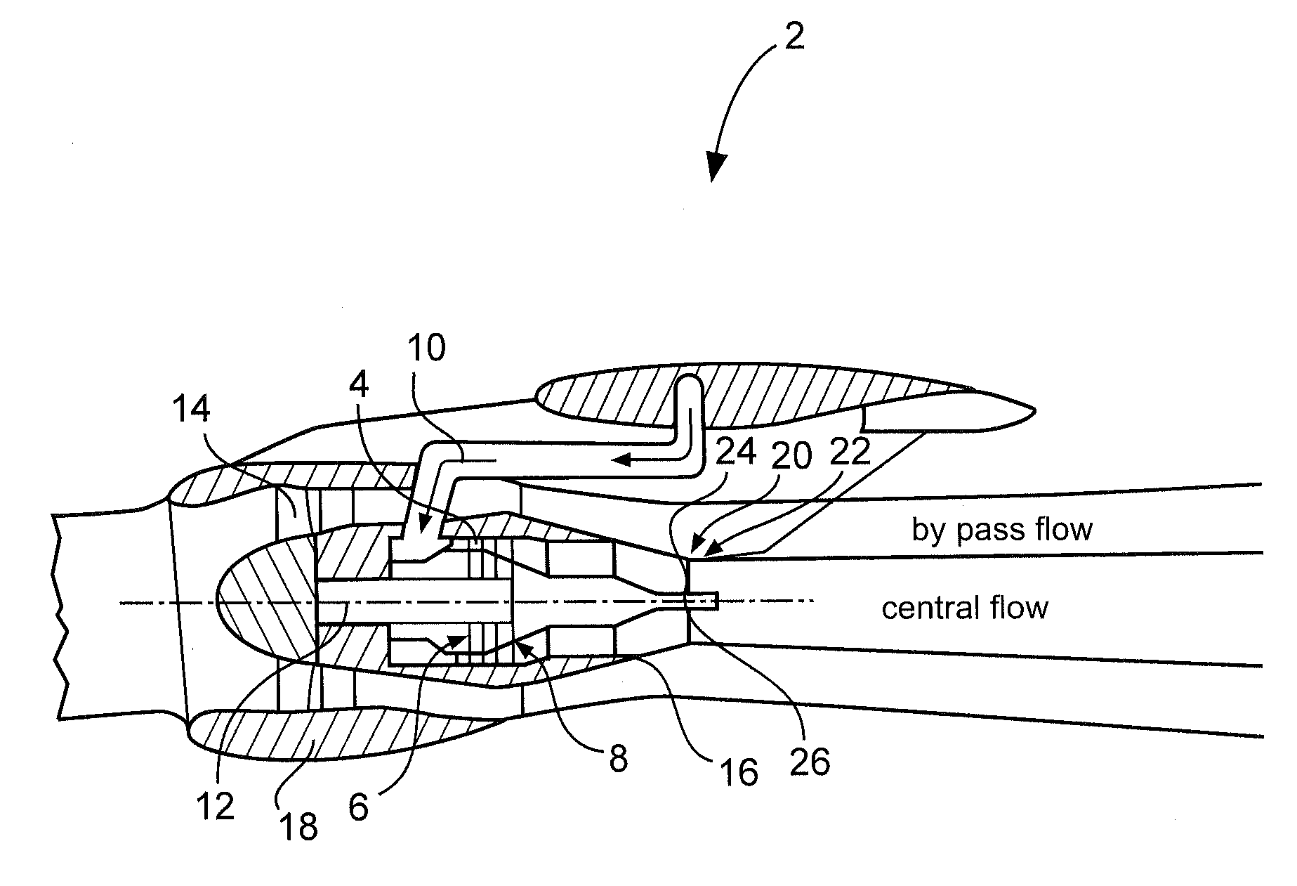
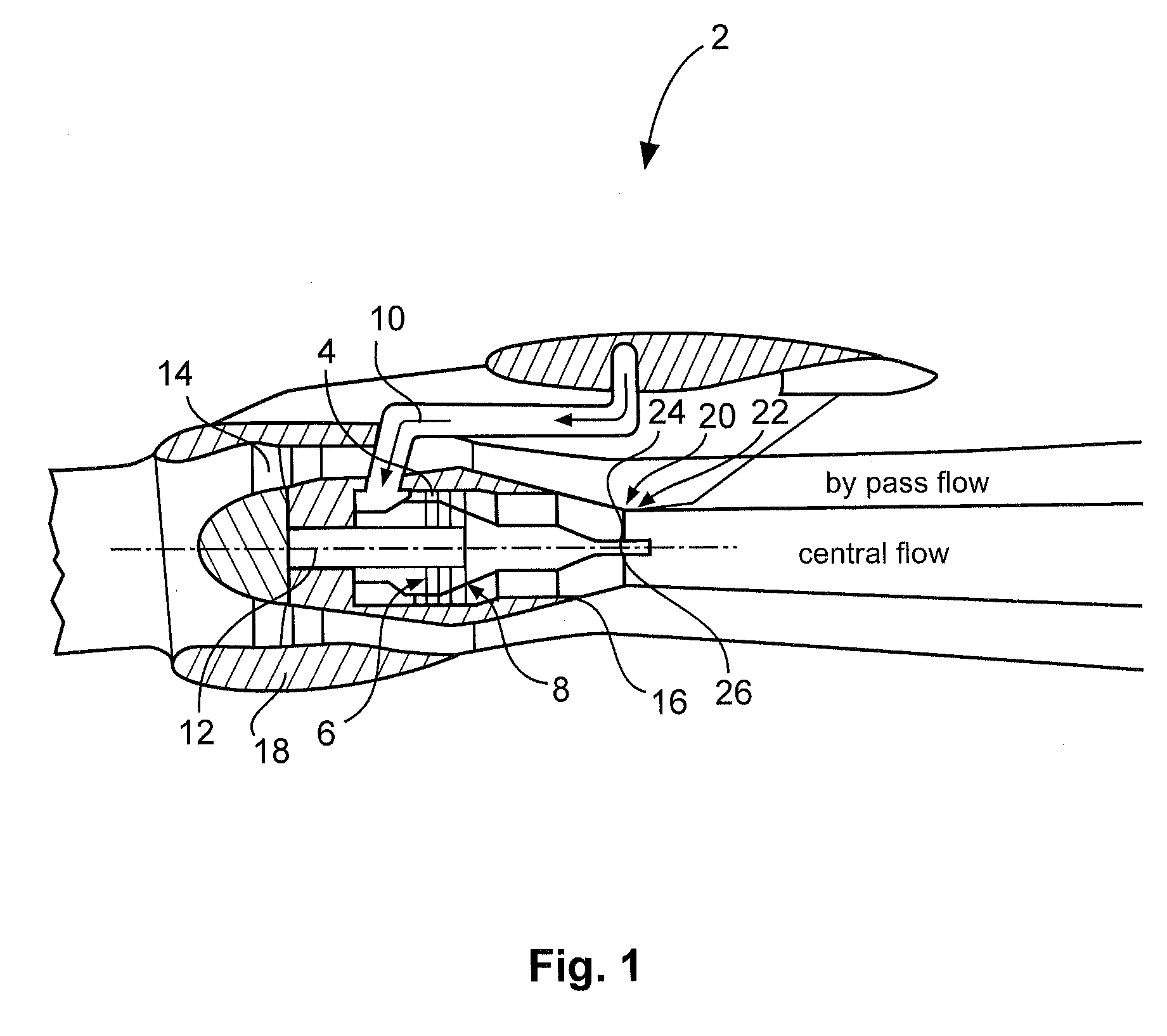
[0024]An engine simulator 2 in FIG. 1 for simulating a bypass engine on a wind tunnel model for an aircraft exhibits a rotatably mounted turbine 4 exemplarily depicted with two stages, which has an inlet 6 and an outlet 8, and is made to rotate by a pressurized fluid from a feed line 10. The fluid gets from the inlet 6 into the turbine 4, there imparts a rotation to the turbine 4 and a ducted fan 14 connected with the turbine 4 via a shaft 12, and flows out of the engine simulator 2 as a central stream through the outlet 8 from a flow-type body 16.

[0025]The ducted fan 14 is enveloped by a jacket 18, which leads to an annular bypass flow streaming by between the flow-type body 16 and jacket 18. In the area of a downstream end of the flow-type body 16 designed as a trailing edge 20, the bypass flow and central stream from the turbine 4 come into contact, so that the two air flows become mixed together in an area at the trailing edge 20. In the thoroughly mixed area, the relieving flui...


PUM


Abstract

An engine simulator for wind tunnel models exhibits a turbine with an inlet for a pressurized fluid and an outlet for a relieved fluid, a flow-type body arranged downstream from the turbine, a jacket that at least partially envelops the flow-type body with the formation of a gap, and at least two electrodes. A downstream end of the flow-type body is provided with a heater coating comprised of a matrix material that contains a conductivity additive and is connected with the electrodes for applying an electrical voltage. This may make it possible to prevent ice formation on the trailing edge of the flow-type body.

Description

CROSS-REFERENCE TO RELATED APPLICATIONS[0001]This application claims the benefit of the filing date of U.S. Provisional Patent Application No. 61 / 491,439 filed May 31, 2011, the disclosure of which is hereby incorporated herein by reference.TECHNICAL AREA[0002]The invention relates to an engine simulator for wind tunnel models, a method for manufacturing a heater coating on a flow-type body of an engine simulator, and the use of a heater coating comprised of a matrix material with a conductivity additive to prevent the accretion of ice on a flow-type body of a wind tunnel model.BACKGROUND OF THE INVENTION[0003]In order to validate a configuration of an aircraft having one or more engines, use is often made of wind tunnel models with engine simulators, which exhibit a ducted fan and flow-through jacket for wind tunnel models of modern commercial aircraft. Simulators like these are operated using a mechanically simple compressor drive, in which compressed air is relieved in a rotatabl...

Claims


Application Information

Patent Timeline
IPC IPC(8): G01M15/00B05D5/00
CPCG01M9/08H05B2203/013H05B3/58G01M15/14
Inventor HUHND, MICHAELDAU, DETLEVMELACHRINOS, ROMANPERNER, HANSFUESER, ANDRE
Owner AIRBUS OPERATIONS GMBH
Learn More