Waste heat recovery mechanism and waste heat recovery apparatus
a waste heat recovery and waste heat technology, applied in mechanical equipment, mechanical energy handling, machines/engines, etc., can solve the problems that the alternator cannot generate electricity, cannot operate by the rotational drive force of the engine when the expander is rotated,
- Summary
- Abstract
- Description
- Claims
- Application Information
AI Technical Summary
Benefits of technology
Problems solved by technology
Method used
Image

Examples
first embodiment
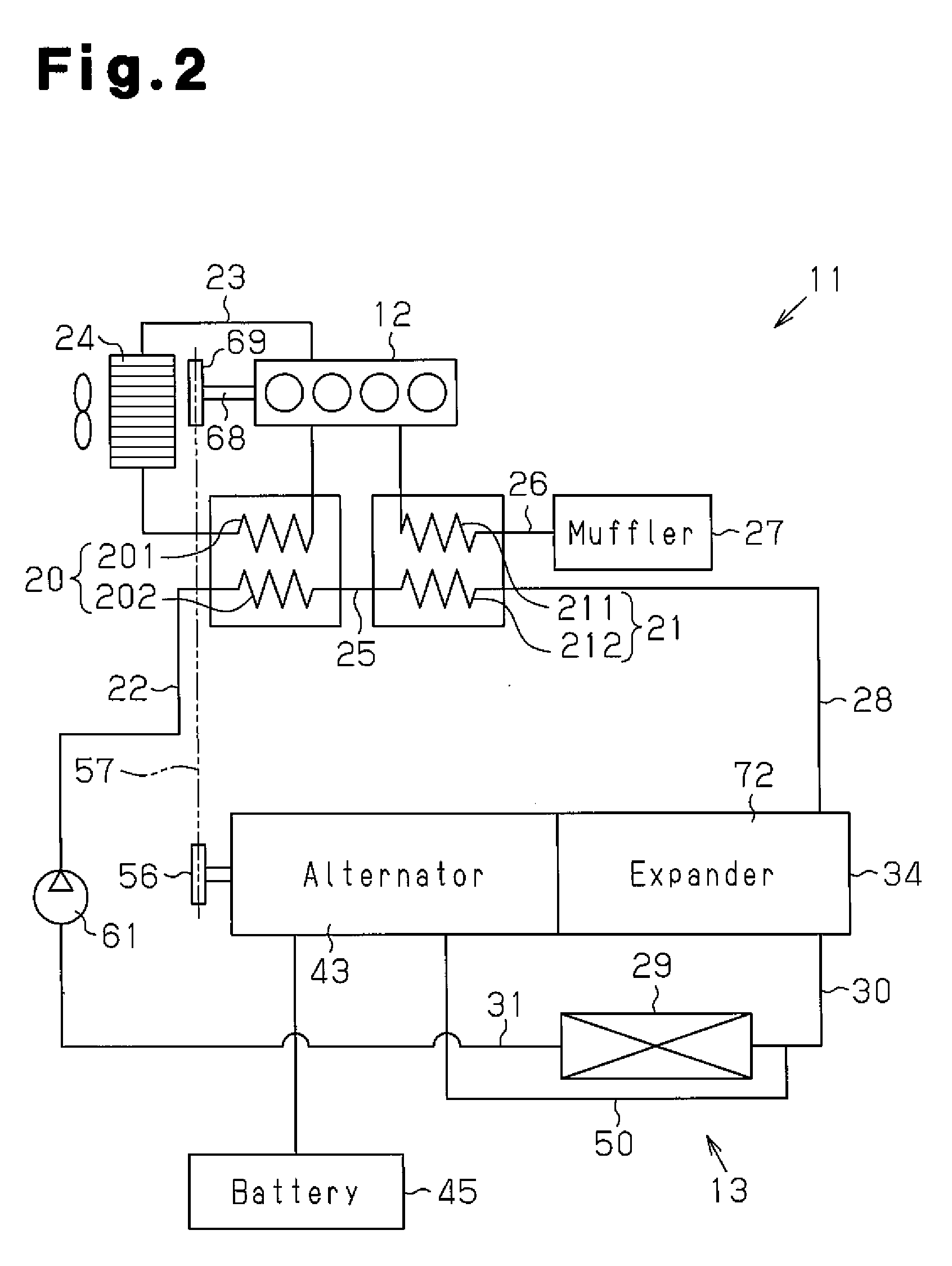
[0013]A first embodiment of the present invention will now be described with reference to FIGS. 1 and 2.
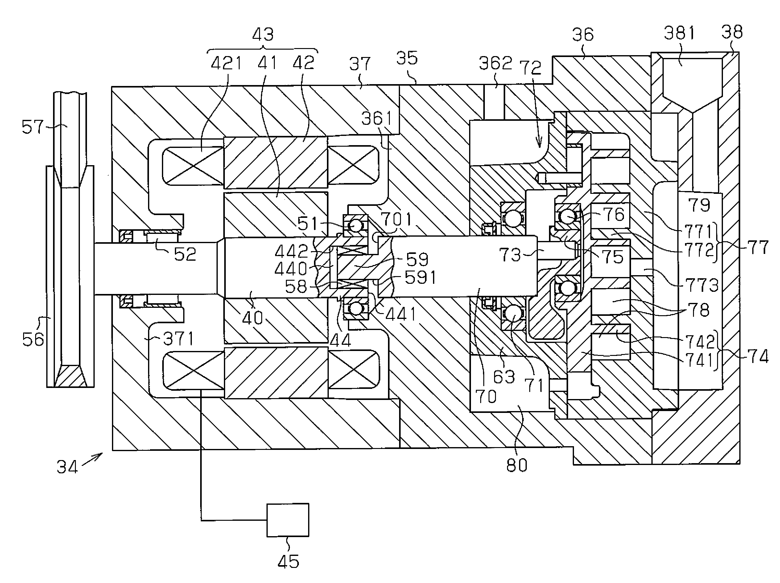
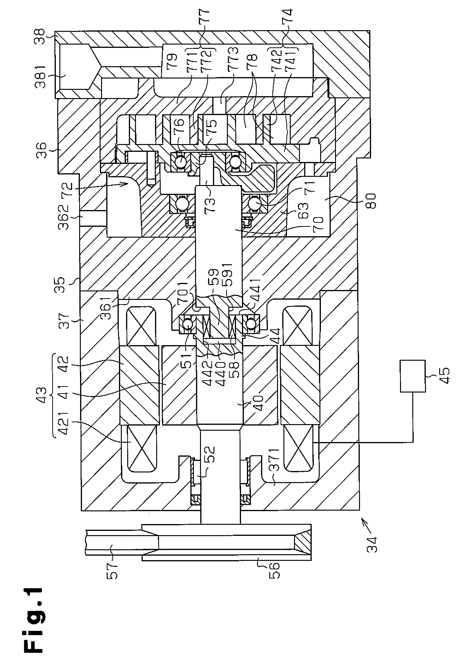
[0014]As shown in FIG. 2, a waste heat recovery apparatus 11 includes an engine 12 (combustion engine) mounted on a vehicle and a Rankine cycle circuit 13, which includes a waste heat recovery mechanism 34. In the Rankine cycle circuit 13, refrigerant is heated by the engine 12, which is a waste heat source, and circulated. As shown in FIG. 1, a housing 35 of the waste heat recovery mechanism 34 includes a center housing member 36, a front housing member 37 secured to the front end (the left end as viewed in FIG. 1) of the center housing member 36, and a rear housing member 38 secured to the rear end (the right end as viewed in FIG. 1) of the center housing member 36.
[0015]A partition 361 is formed in the front end (the left end as viewed in FIG. 1) of the center housing member 36, and a front end wall 371 is formed at the front end (the left end as viewed in FIG. 1) of the front ...
second embodiment
[0037]A second embodiment will now be described with reference to FIGS. 3 to 4. The same reference numerals are given to those components that are the same as the corresponding components of the first embodiment, and detailed explanations are omitted.
[0038]As shown in FIG. 3, a side plate 62 is fixed in the center housing member 36 to face the partition 361. A pump chamber 64 is formed between the partition 361 and the side plate 62, and a gear pump 67 is located in the pump chamber 64. The output shaft 70 extends through the partition 361 and the side plate 62.
[0039]The gear pump 67 includes a drive gear 65, which is fixed to the output shaft 70, and a driven gear 66, which meshes with the drive gear 65. A suction passage 46 is connected to the suction side (the lower side as viewed in FIG. 3) of the pump chamber 64, and a delivery passage 47 is connected to the delivery side (the upper side as viewed in FIG. 3) of the pump chamber 64. The suction passage 46 constitutes a part of t...
third embodiment
[0045]A third embodiment will now be described with reference to FIG. 5. The same reference numerals are given to those components that are the same as the corresponding components of the second embodiment, and detailed explanations are omitted.
[0046]An insertion space 443 is recessed in the bottom of the in-cylinder space 440 of the cylindrical portion 44. The insertion space 443 receives the small diameter end 59 of the output shaft 70. A plane bearing 60, which is an auxiliary bearing, is located between the outer circumferential surface of the distal end of the small diameter end 59 and the inner circumferential surface of the insertion space 443. The plane bearing 60 is closer to the distal end of the output shaft 70 than the torque limiter 58.
[0047]The gas pressure in the radial direction of the gaseous refrigerant in the expander 72 is transmitted to the output shaft 70 via the bearing 76. The position X of the bearing 76 is a point to which the force of the gas pressure in t...
PUM
 Abstract
Description
Claims
Application Information
 - R&D
- Intellectual Property
- Life Sciences
- Materials
- Tech Scout
- Unparalleled Data Quality
- Higher Quality Content
- 60% Fewer Hallucinations
Browse by: Latest US Patents, China's latest patents, Technical Efficacy Thesaurus, Application Domain, Technology Topic, Popular Technical Reports.
© 2025 PatSnap. All rights reserved.Legal|Privacy policy|Modern Slavery Act Transparency Statement|Sitemap|About US| Contact US: help@patsnap.com