
Variable shaped lamp shade of LED lamp

a technology of led lamps and lampshades, which is applied in the direction of point-like light sources, lighting and heating apparatuses, lighting device details, etc., can solve the problems of insufficient illumination, low intensity of led illumination, and usually no design for a more efficient light distribution of led light sources, so as to improve illumination intensity, save electric power, and uniform illumination

Active Publication Date: 2012-11-29
CHIH YANG CHANG +1
View PDF2 Cites 40 Cited by
  • Summary
  • Abstract
  • Description
  • Claims
  • Application Information

AI Technical Summary

Benefits of technology

"The present invention provides a variable shaped lamp shade for LED lamps that uses a special optical structural design to control the light passing through the lamp shade and diffuse the light uniformly within a specific range of angles. This design enhances the intensity of illumination, provides a uniform illumination, and saves electric power. The lamp shade is made of a translucent material and includes at least one strip-shaped optical refraction unit with a curved surface without an inflection point and a small curved surface to prevent glares. The lamp shade can be made of a fire-resisting and durable material such as polycarbonate. The special optical structural design of the lamp shade controls the light passing through it and diffuses the light uniformly within a specific range of angles. The lamp shade can be designed for different shapes of LED lamps, such as strip-shaped, fan-shaped, or ring-shaped."

Problems solved by technology

However, the intensity of the illumination of the LED is relatively low and the illumination is not uniform enough, such that its application as a lamp still requires a lamp shade to perform a secondary light distribution.
However, most LED lamp shades available in the market and used for the secondary light distribution emphasize on the protection of the light source only, but such conventional LED lamp shades usually provide no design for a more efficient light distribution of the LED light source.
Even though some LED lamp shades may come with an anti-glare design or a simple secondary light distribution design, a common design with a spherical surface generally results in a less efficient light distribution effect.
In addition, the lamp shade used for the traditional light source (incandescent lamp or fluorescent tube) emphasizes on the protection and decoration of the lamp only, but seldom provides a functional effect or improves the light distribution of the light source.
The design of some lamp shades may take the light distribution of the lamp shade into consideration, but the conventional lamp shade only comes with a simple light distribution design, such as using a cylindrical surface as the curved surface of the lamp shade, and such cylindrical surface has no or little change of curvature that can just proportionally narrow the light emitted from the traditional light source, but such lamp shade cannot be applied to the lamp of the LED light source at all.
More specifically, the LED light source is close to a point light source whose emitting light has the greatest brightness at the middle and a decremented brightness towards the periphery, so that when the lamp shade for the traditional light source is applied to a lamp of the LED light source, the LED light source will be further narrowed proportionally, and thus resulting in a phenomenon of a too-bright middle (or a non-uniform light illumination).
To improve this problem, related designers and manufacturers adopt a solution of installing more LEDs, but such design of installing more LEDs further introduces the drawbacks of high power consumption and incompliance with the cost-effectiveness and the power saving effect of the LED lamps.

Method used


Image

  • Variable shaped lamp shade of LED lamp
  • Variable shaped lamp shade of LED lamp
  • Variable shaped lamp shade of LED lamp

Examples


Embodiment Construction

[0033]The objects, characteristics and effects of the present invention will become apparent with the detailed description of the preferred embodiments and the illustration of related drawings as follows.

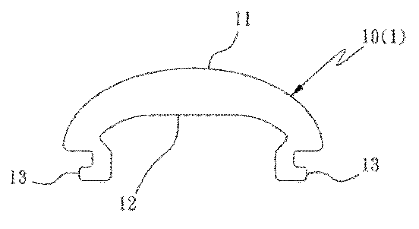
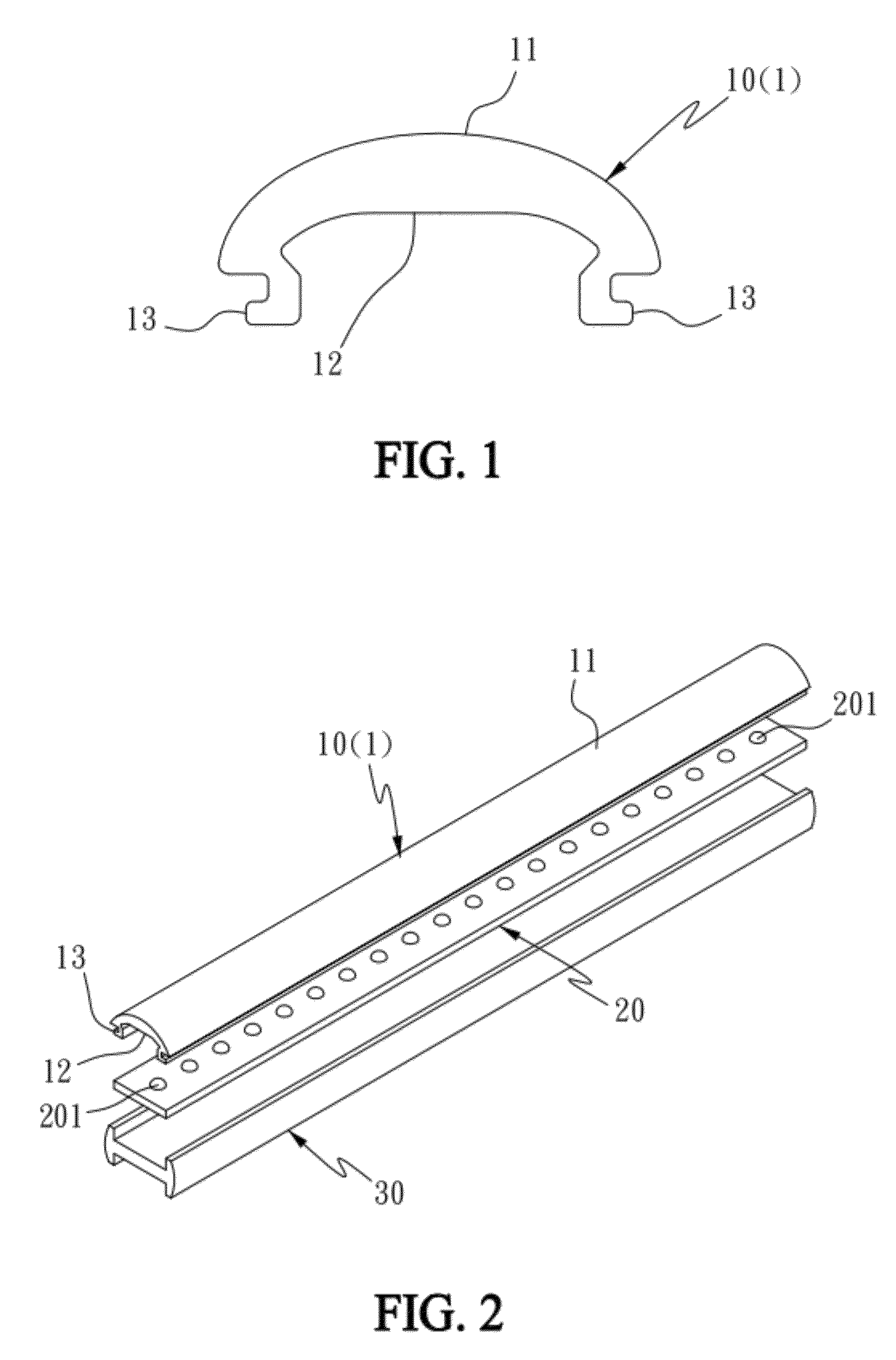
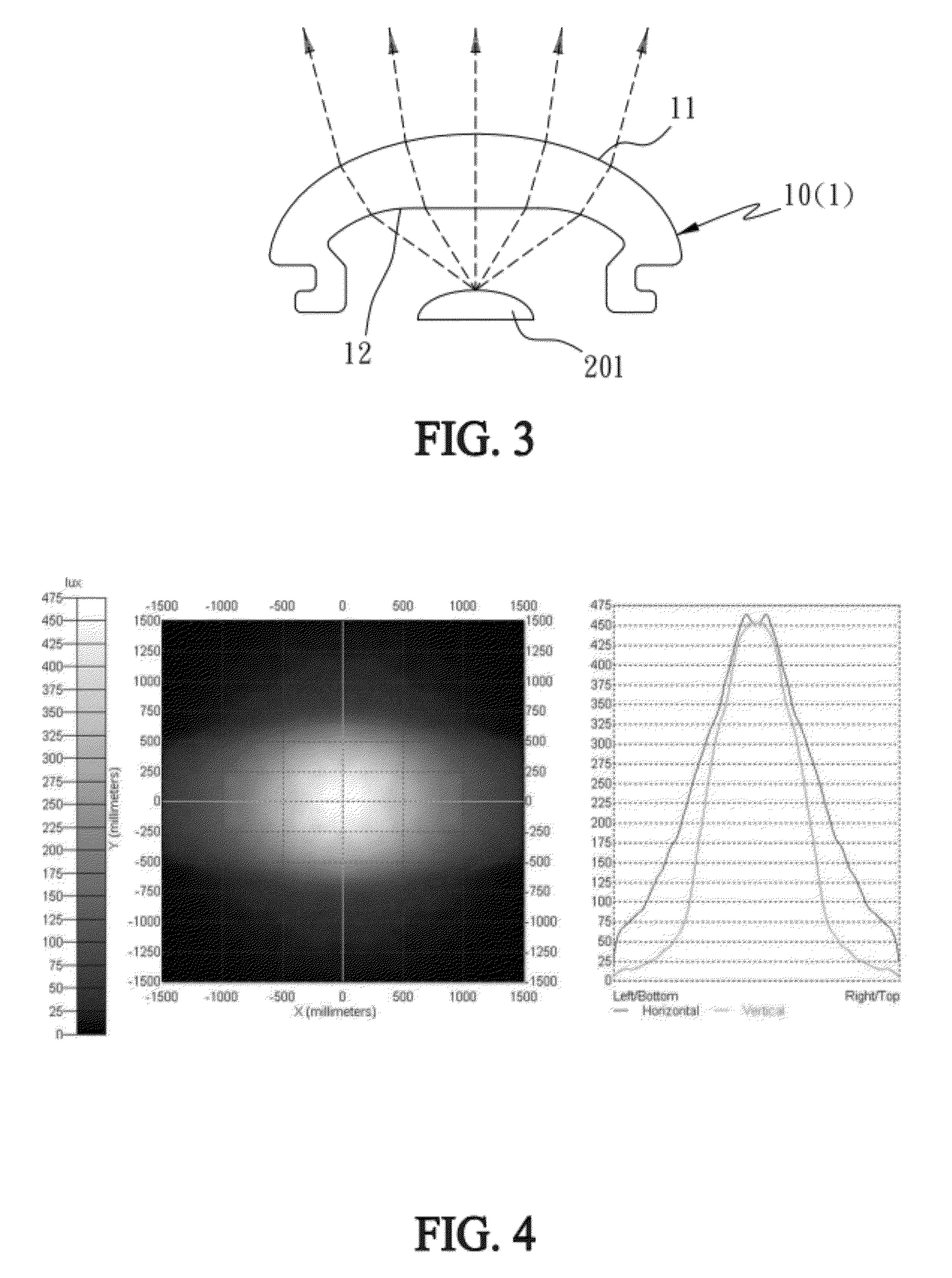
[0034]With reference to FIGS. 1 and 2 for a variable shaped lamp shade of an LED lamp in accordance with a first preferred embodiment of the present invention, the lamp shade 10 is made of a translucent material matched with an LED lamp strip 20 and a lamp holder 30, and the lamp shade 10 comprises at least one strip-shaped optical refraction unit 1, and each optical refraction unit 1 has an external refractive surface 11, an internal refractive surface 12 corresponding to the external refractive surface 11, and an assembling structure 13 for matching the lamp holder 30, and the optical refraction unit 1 has a cross-sectional structure substantially in an Ω shape, wherein the external refractive surface 11 of the optical refraction unit 1 is a curved surface without an inflection po...


PUM


Abstract

In a variable shaped lamp shade of an LED lamp, the lamp shade is made of a translucent material matched with an LED lamp strip and a lamp holder and includes at least one strip-shaped optical refraction unit having an external refractive surface, an internal refractive surface corresponding to the external refractive surface, and an assembling structure for matching the lamp holder. The external refractive surface or internal refractive surface is a curved surface without an inflection point and the curved surface has a constant or gradually changing curvature; and a non-curved surface is formed on the other side. The variable shaped lamp overcomes the problems of conventional LED lamp strips having a low illumination and a non-uniform illumination caused by a direct projection or an installation of a conventional lamp shade, and a low light utility caused by a too-large illumination range.

Description

CROSS-REFERENCE TO RELATED APPLICATION[0001]This application is a divisional patent application of U.S. application Ser. No. 12 / 941,934 filed on Nov. 8, 2010, the entire contents of which are hereby incorporated by reference for which priority is claimed under 35 U.S.C. §120.FIELD OF THE INVENTION[0002]The present invention relates to a lamp shade of an illumination lamp, in particular to a variable shaped lamp shade of a light emitting diode (LED) lamp.BACKGROUND OF THE INVENTION[0003]Light emitting diode (LED) has become a new-generation light source for illumination due to its advantages such as power saving and long lifespan, and the LED is used extensively as a light source in many different fields and it gradually replaces traditional incandescent lamps and fluorescent tubes. For example, a long striped substrate including a plurality of high-brightness light-emitting diodes (HB-LED) arranged in a row is used to replace the fluorescent tube. However, the intensity of the illum...

Claims


Application Information

Patent Timeline
Patent Type & Authority Applications(United States)
IPC IPC(8): F21V13/02
CPCF21S4/008F21Y2103/003F21Y2101/02F21V5/00F21S4/28F21Y2103/10F21Y2115/10
Inventor CHANG, CHIH-YANGLIU, HSING-KUEI
Owner CHIH YANG CHANG
Learn More