
Optical filter, optical filter module, and photometric analyzer

a technology of optical filter and optical filter module, which is applied in the direction of optical radiation measurement, instruments, spectrometry/spectrophotometry/monochromators, etc., can solve the problems of reducing the accuracy of controlling the distance between the reflection films, thus becoming charged, etc., and achieves accurate spectroscopic characteristics, reduced accuracy of controlling the distance, and high accuracy

Inactive Publication Date: 2012-11-29
SEIKO EPSON CORP
View PDF6 Cites 15 Cited by
  • Summary
  • Abstract
  • Description
  • Claims
  • Application Information

AI Technical Summary

Benefits of technology

The invention is an optical filter that solves problems related to charging and maintains the distance between reflection films. The filter includes a first substrate, a second substrate, a first reflection film, a second reflection film, a first electrode, a second electrode, and a light receiving unit. The first electrode covers the first reflection film and is electrically connected to it, while the second electrode is on the second substrate and is opposed to the first electrode. The distance between the first electrode and the second reflection film is larger than the distance between the first reflection film and the second electrode. The first reflection film and the second reflection film do not contact or stick to each other, and a gap between them is maintained. A conducting film or an insulating film may be formed on the surface of the second reflection film to prevent charging. The technical effect of the invention is to reduce the accumulation of charge on the surfaces of the electrodes and maintain the distance between reflection films.

Problems solved by technology

However, the protective film according to JP-A-1-300202 is formed using an insulating material, and there is a problem that a charge is accumulated on the surface of the insulating material and the reflection film thus becomes charged.
This causes a reduction in the accuracy of controlling the distance between the reflection films.

Method used


Image

  • Optical filter, optical filter module, and photometric analyzer
  • Optical filter, optical filter module, and photometric analyzer
  • Optical filter, optical filter module, and photometric analyzer

Examples


first embodiment

Advantages of First Embodiment

[0107]According to the embodiment, there are at least the following advantages.

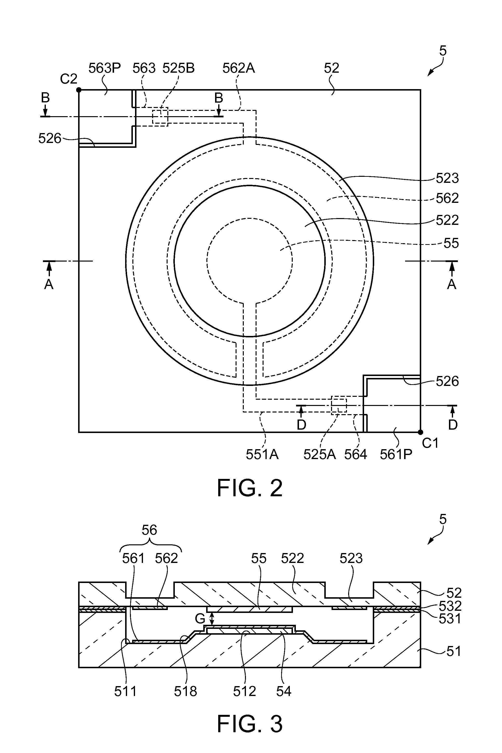
[0108]In the etalon 5 as an optical filter, the first electrode 561 is formed to cover the first reflection film 54, and the first electrode 561 and the second reflection film 55 are electrically connected at the same potential.

[0109]Accordingly, no charge is accumulated on the surfaces of the opposed first electrode 561 and second reflection film 55, and charging on both surfaces may be prevented. Thus, an extra force such as a repulsive force or an attractive force does not act between the first reflection film 54 and the second reflection film 55 and a reduction in the accuracy of controlling the distance between the reflection films due to charging may be suppressed.

[0110]Further, in the driving of the electrostatic actuator 56 in the etalon 5, the pull-in phenomenon that a pulling force sharply increases when the gap dimension between the first electrode 561 and the seco...

modified examples

[0116]FIGS. 8 to 11 are sectional views showing modified examples of the configuration of the etalon. In the following explanations, the same configurations as those of the first embodiment have the same reference signs in the drawings and their duplicate explanation will be omitted.

[0117]An etalon 6 shown in FIG. 8 is different from the etalon of the first embodiment in that a conducting film 61 covering the second reflection film 55 of the movable substrate 52 from the front surface to the side surfaces is provided.

[0118]The conducting film 61 is formed of a light-transmissive material, for example, an ITO film.

[0119]Because of this structure, no charge is generated on the surface of the conducting film 61 and no charge is generated at the side of the second reflection film 55. Accordingly, no attractive force or repulsive force acts between the reflection films, and the gap dimension between the reflection films may be accurately controlled by driving of the actuator. Further, th...

second embodiment

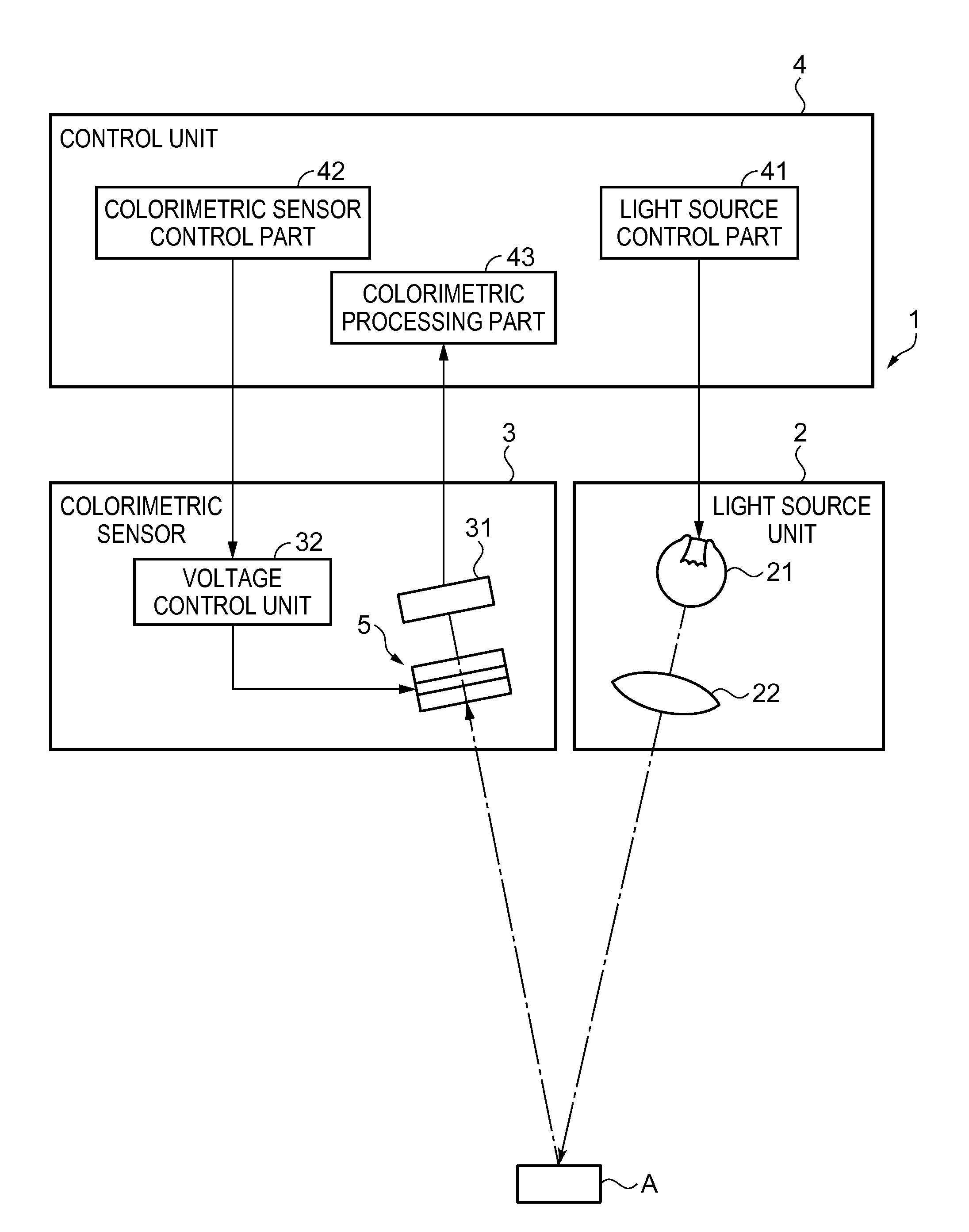
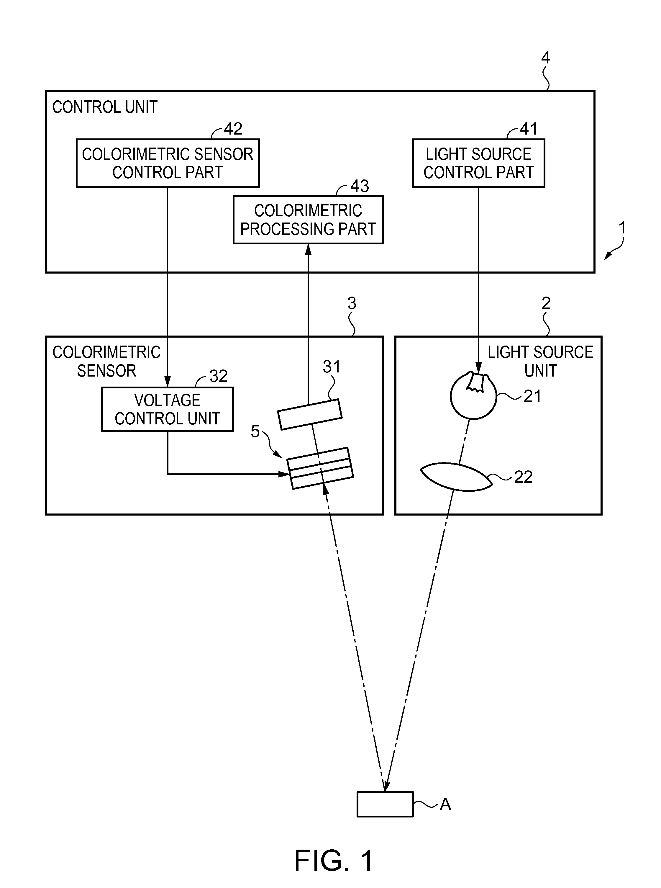
[0132]Below, an example of the gas detector will be explained according to the drawings.

[0133]FIG. 12 is a sectional view showing an example of the gas detector including the etalon.

[0134]FIG. 13 is a block diagram showing a configuration of a control system of the gas detector.

[0135]The gas detector 100 includes a sensor chip 110, a channel 120 having a suction port 120A, a suction channel 120B, an eject channel 120C, and an ejection port 120D, and a main body part 130 as shown in FIG. 12.

[0136]The main body part 130 includes a detection unit (optical filter module) including a sensor part cover 131 having an opening to which the channel 120 is detachably attached, an ejecting unit 133, a housing 134, an optical unit 135, a filter 136, the etalon (tunable interference filter) 5, a light receiving device 137 (light receiving unit), etc., a control unit 138 that processes a detected signal and controls the detection unit, and a power supply unit 139 that supplies power. Further, the ...


PUM


Abstract

An optical filter includes fixed substrate, a movable substrate opposed to the fixed substrate, a first reflection film provided on a surface of the fixed substrate facing the movable substrate, a second reflection film provided on the movable substrate and opposed to the first reflection film across a gap, a first electrode formed to cover the first reflection film and to extend beyond an outer circumference of the first reflection film, and a second electrode provided on a surface of the movable substrate facing the fixed substrate and opposed to a part of the first electrode, and the first electrode is formed of a light-transmissive material, and the first electrode and the second reflection film are electrically connected at the same potential.

Description

BACKGROUND[0001]1. Technical Field[0002]The present invention relates to an optical filter, an optical filter module, and a photometric analyzer.[0003]2. Related Art[0004]A known optical filter extracts light having a specific wavelength from light having plural wavelengths. An example of such an optical filter is a tunable interference filter.[0005]A tunable interference filter is an optical filter in which reflection films (optical films) formed on substrates oppose one another and a gap dimension between the reflection films is changed by an external force to transmit light having a wavelength corresponding to the gap dimension.[0006]JP-A-1-300202 (see FIG. 1(b)), discloses a configuration in which a titanium oxide thin film layer, a silver thin film layer, and a protective film are sequentially stacked as a reflection film on a substrate. The protective film is provided for preventing deterioration due to sulfuration and humidity of the silver thin film layer because of exposure...

Claims


Application Information

Patent Timeline
Patent Type & Authority Applications(United States)
IPC IPC(8): G02B26/00G01J3/46
CPCG01J1/04G01J3/26G01J1/0488G01J2003/1247G02B26/001
Inventor SANO, AKIRAMATSUNO, YASUSHI
Owner SEIKO EPSON CORP
Learn More